PCAN-PC/104 – User Manual
10
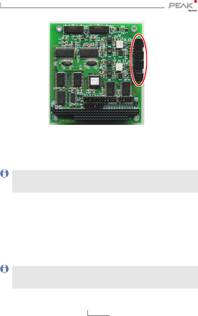
Figure 3: Connectors for the flat cables to the CAN connectors,
J3 for CAN channel one (lower position),
J4 for CAN channel 2 (upper position, Dual Channel version only)
4. Close the computer's casing.
Note: Before switching on the computer, please follow the
procedure for modifying the computer's BIOS settings
described in the following section.
2.3 Modifying the Computer's BIOS Settings
To ensure a flawless operation of the PCAN-PC/104 card it is
necessary that you indicate the used interrupt(s) in the BIOS setup
of the computer. You avoid that the corresponding resources are
automatically assigned to other devices and resulting conflicts.
Note: Due to a diversity of existing BIOS setup versions for
computers we cannot give detailed instructions here. Instead
we indicate common setting names.


