PCAN-PC/104 – User Manual
7
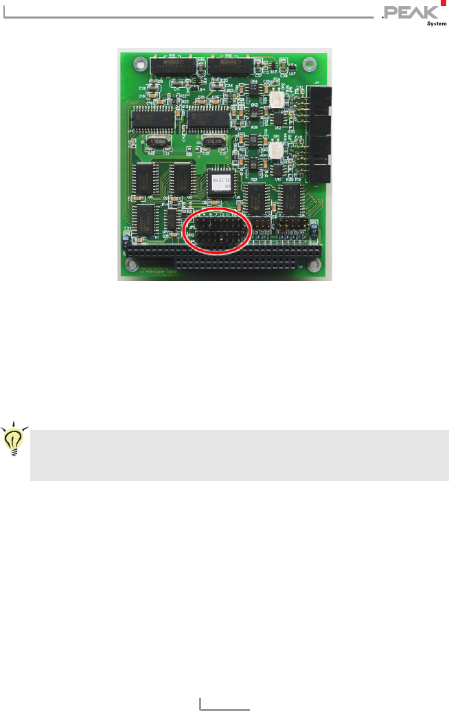
Figure 1: Position of the jumper fields for setting the interrupts,
JP1 for CAN channel 1 (lower jumper field),
JP2 for CAN channel 2 (upper jumper field,
Dual Channel version only)
It is possible to share the same interrupt between two existing CAN
channels. Therefore you can configure the same interrupt, when
using two PCAN-PC/104 cards in the same computer.
Tip: We suggest to configure different interrupts as long as
resources allow it and use interrupt sharing only, if this is not
the case.
I/O Address Range
Each CAN channel must be assigned to an unique I/O address range
in the computer. An address space from 200h up to 39Fh and 3E0h
to 3FFh (h = hexadecimal) is available. PCAN-PC/104 uses 32
addresses beginning from the configured base address. The
configuration is done on jumper field JP3 for CAN channel 1 and
jumper field JP4 for CAN channel 2 (latter only with the Dual
Channel version). One or several jumpers are needed for each
jumper field.


