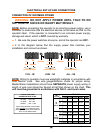
COM
COM
COM
24V
AC
24V
AC
ALT
RDO
OPN
CRO
FRE
OPN
CLO
STO
COM
COM
COM
OPN
PHO
CLO
PHO
SHW
REV
OPN
EDG
CLO
EDG
MST
OPN
MST
CLO
COM
COM
COM
OPEN
PUSH
FREE
EXT
ALT
RADIO
OPN/
CLO
RADIO
OPEN
CLOSE
PUSH
STOP
PUSH
CLOSE
PHOTO
OPEN
PHOTO
LD1 8
LD1 0
LD1 1
LD1 2
LD1 5
LD1 4
LD1 6
LD1 7
LD1 3
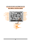
OPEN
CLOSE
STOP
OPEN CLOSE
FORCE
ADJUSTMENT
AUTO
RECLOSE
TIMER
OFF MAX
MID
LIMIT
REV
LOOP
OPN
EDGE
CLO
EDGE
RH OPN
LH CLO
LIM IT
RH CLO
LH OPN
LIM IT
MOTOR
OPEN
MOTOR
CLOSE
SHADOW
LOOP
LD19
LD2
LD3
LD4
LD5
LD6
LD8
LD9
LD7
12345
POWER
LD1
P3
P4
TB 1 TB 2
U1
U2
U4
ALT
RADIO
OPN/
CLO
RADIO
OPEN
CLOSE
PUSH
STOP
PUSH
LD11
LD12
LD15
LD14
LD16
LD17
OPEN
CLOSE
STOP
OPEN
12345
ON
OFF
12345
ON
OFF
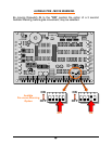
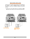
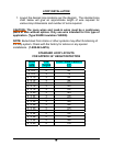
For Normally
Open Stop
Button
For Normally
Closed Stop
Button
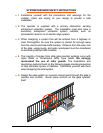
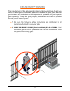
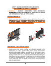
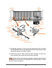
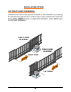
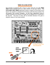
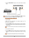
Ÿ WARNING: STAY CLEAR OF ALL MOVING PARTS AND
ELECTRICAL COMPONENTS OF THE OPERATOR WHILE TESTING!
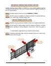
NOTE:
The first time the gate operator is run after the power is turned
on; a 3 second warning will sound before the operator starts.
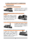
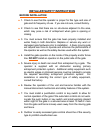
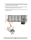
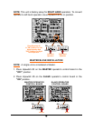
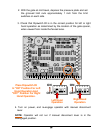
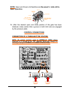
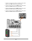
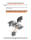
5. Open the gate electrically using the THREE BUTTON control station
mounted on the control board.
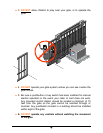
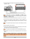
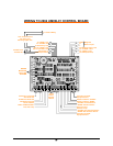
BOARD MOUNTED CONTROL STATION
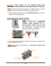
NOTE: If Dipswitch #3 is in the “ON”
position for use with a NORMALLY
CLOSED “STOP” BUTTON, then the
board mounted “STOP” button must be
held depressed in order to use the open
and close buttons. Releasing the stop
button will then stop the operator.
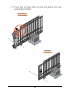
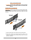
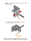
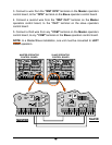
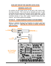
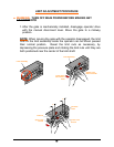
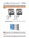
6. If the gate travels in the correct direction and stops on the open limit
switch, proceed to step #11.
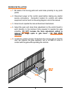
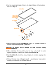
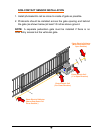
NOTE:
Open and Close Limit Switches are Reversed for Slide Left to
Open Operation.
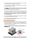
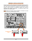
OPEN LIMIT SWITCH
For Slide Right To Open
Operation
Pressure Plate
Limit nut
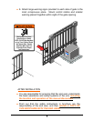
Limit nut
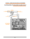
CLOSE LIMIT SWITCH
for slide right to open
operation
Limit
Shaft
Limit switch
housing