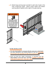
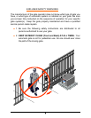
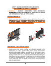
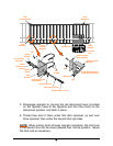
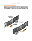
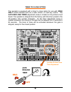
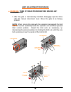
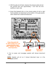
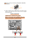
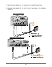
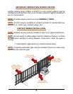
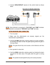
2. Connect contact sensor edges to the control board as shown in the
illustration below.
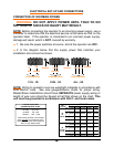
NOTE:
Leading edge is connected to “CLO EDG” and “COM” terminals.
Trailing edge, Post Mounted edge and Fence Mounted edge are connected to
“OPN EDG” and “COM” terminals.
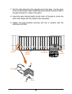
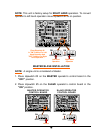
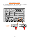
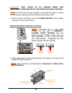
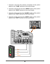
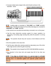
3. After sensors are mounted and electrically connected, turn on the power.
4. Test the close obstruction sensing system for proper operation, by
depressing the leading edge sensing strip while the operator is running
closed.
NOTE:
The operator should stop and reverse a short distance and then
stop.
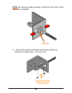
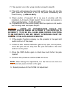
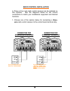
5. Run the operator to the close limit.
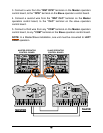
6. Test the open obstruction sensing system by depressing one of the other
three edge sensors while the gate is opening.
NOTE
: The operator should repeat the STOP AND REVERSE procedure.
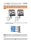
8. Run operator to the close limit and repeat step #6 for the other two
edges.
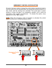
NOTE: If an edge is activated twice or a second edge is activated
before a limit is hit (full open or close) operator will stop and sound a
warning horn. To reactivate system turn operator power switch off
then on.
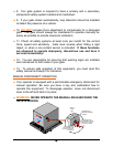
REV
OPN
EDG
CLO
EDG
MST
OPN
MST
CLO
COM
COM
COM
OFF MAX
SHADOW
LOOP
LD7
12345
Leading Edge
Trailing Edge
CONTACT SENSOR CONNECTION