ST-133B Addendum
May 12, 2004 2 of 2 Princeton Instruments
CE:\Manuals\Controller\ST-133B\ST-133B Addendum.doc
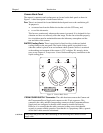
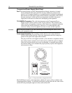
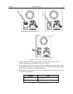
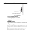
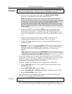
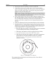
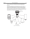
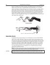
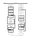
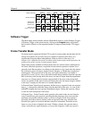
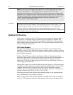
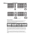
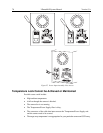
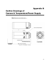
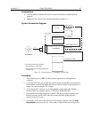
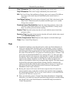
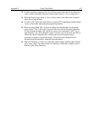
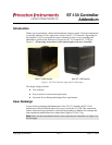
Figure 2. Carrying the ST-133B
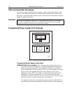
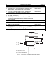
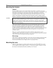
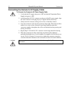
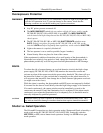
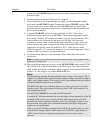
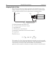
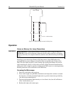
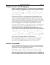
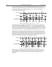
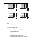
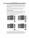
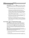
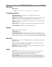
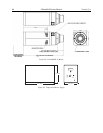
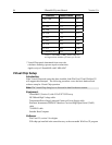
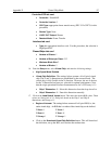
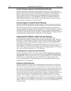
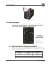
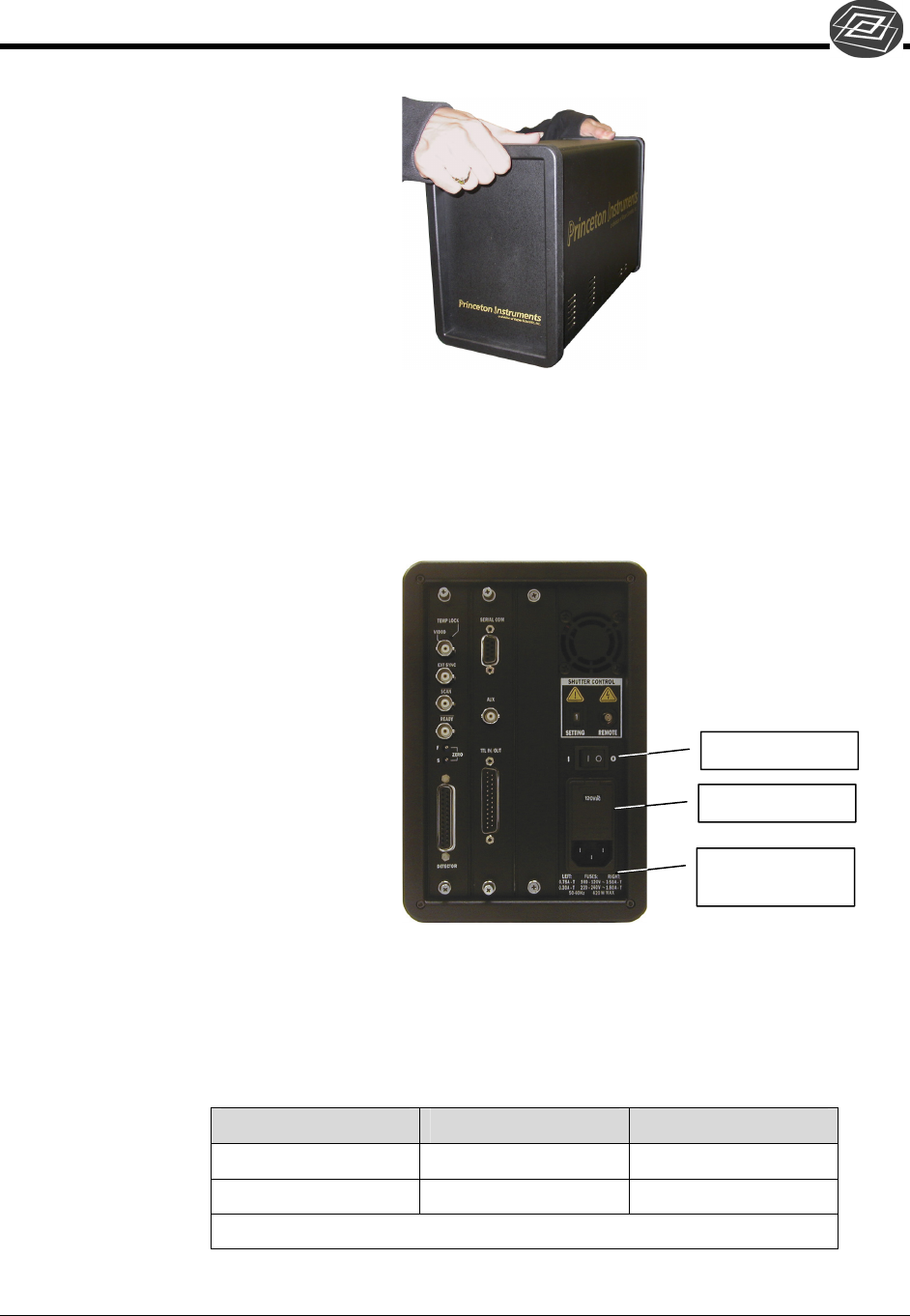
ST-133B Power Switch
For the ST-133B, the power switch has been re-located to the back of the Controller and
is positioned above the power module. To eliminate unwanted light sources around
optical setups, the power switch no longer includes a built-in LED.
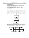
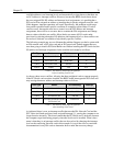
Figure 3. ST-133B Back Panel
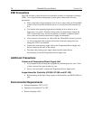
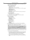
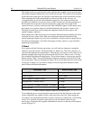
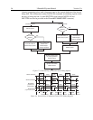
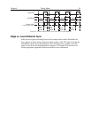
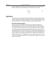
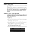
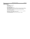
ST-133B Power Rating and Fuse Requirements
This manual may include a Fuse and Voltage table that refers to the ST-133A; ignore
this table and refer to the Fuse/Voltage label on the back of the ST-133B or to the table
below for the correct information.
LEFT Fuse Voltage RIGHT Fuse
~0.75A-T 100-120V ~3.50A-T
~0.30A-T 220-240V ~1.80A-T
50-60 Hz 420 W MAX
Power Switch
Power Module
Fuse/Voltage
Label