58 I-PentaMAX System Manual Version 3.A
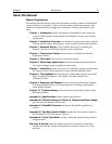
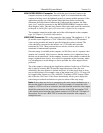
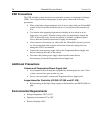
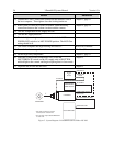
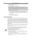
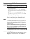
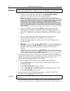
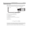
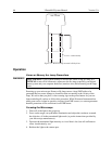
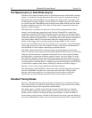
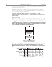
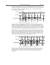
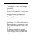
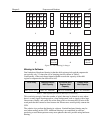
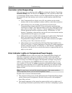
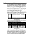
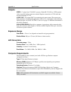
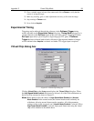
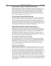
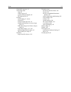
less than one divided by the scan time. The minimum exposure time is equal to the
amount of time needed to read out the storage half of the array, unless an external shutter
is used. Figure 20 shows an example where t
exp
+ t
w1
+ t
c
< t
R
. t
w1
is the time the
controller waits for the first pulse.
NOTSCAN
SHUTTER
Read Read Read
External Sync
(negative polarity shown)
Read
Data not
stored
Data
stored
Data
stored
Data
stored
t
exp
t
w1
t
R
50ns min.pulse between frames
Figure 20. Frame Transfer where t
exp
+ t
w1
+ t
c
< t
R·
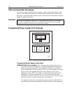
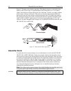
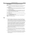
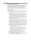
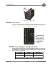
Although in Figure 20 and Figure 21, SHUTTER, one of the software programmable
outputs available at the LOGIC OUT connector, is low before the External Sync pulse
is received, remember that in most cases there is no mechanical shutter present, so light
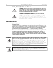
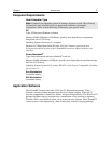
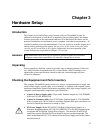
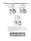
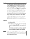
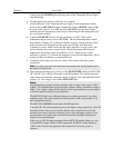
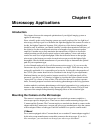
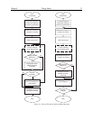
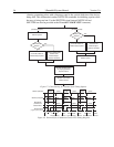
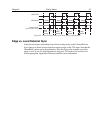
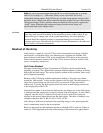
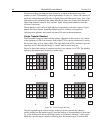
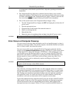
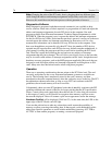
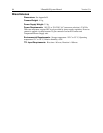
falls on the array during the entire readout. Figure 21 shows the timing of the experiment
if the exposure time is set to a value greater than the readout time (t
exp
+ t
w1
+ t
c
> t
R
).
The presence of an electronic shutter in frame-transfer systems allows exposure times
that are less than the readout time of the device to be achieved. The frame rates of frame-
transfer devices are much higher than full-frame CCDs of comparable resolution. The
high speed of the electronic shutter allows the camera to operate in frame transfer mode
with very little time taken in exposure if flash illumination is used. .
NOTSCAN
SHUTTER
Read Read Read
External Sync
(negative polarity shown)
Read
Data
stored
Data
stored
Data
stored
t
exp
t
w1
t
R
t
c
Data
stored
Figure 21. Frame Transfer where t
exp
+ t
w1
+ t
c
> t
R
Figure 21 shows a case where the External Sync pulse arrives during readout of the
array. Depending on the frequency of this signal and the frame rate of the camera, this
pulse could also arrive after the readout. Figure 22 shows the timing under these
conditions.