


ADC1 Instruction Manual Page 11
Operation
Mode Display
Mode Switch Meter Display
Meter Switch
Left
First Stage Gain
Right
First Stage Gain
Left
Variable/Calibrated
Gain Switch
Right
Variable/Calibrated
Gain Switch
Left Gain
Preset
Right Gain
Preset
Left Gain
Right Gain
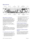
Mode Switch and Display
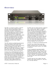
The ADC1 can be programmed to function in
a variety of conversion modes, including
sample rates, bit depths, and output formats,
using internal and/or external clock sources.
This programming is all done through the
Mode Switch. The Mode Display shows the
selected mode in a concise format.
The Mode Switch is a momentary toggle
switch. There are two ways of operating the
mode switch:
1. Press
2. Press and Hold
Pressing the Mode Switch momentarily and
then releasing it results in a particular change
to the ADC1 conversion mode, while pressing
and holding the switch results in a different
change.
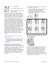
To program the conversion mode
• Press the Mode Switch up repeatedly to
cycle through the clock source and sample
rate options for the Main Outputs.
• Press the Mode Switch down repeatedly to
to cycle through the sample rate and bit
depth options for the Aux Output.
• Press and hold the Mode Switch down for
approximately 3 seconds to switch
between AES/EBU and ADAT mode for the
Optical Output.
• Press and hold the Mode Switch up for
approximately 3 seconds to reset the
ADC1 to Factory Default settings.
Details about all of these actions follow.
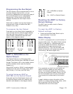
Programming the Outputs
Pressing up repeatedly on the mode switch
cycles through the clock source and sample
rate options for the Main Outputs. The Main
Outputs can be set to operate at a fixed
frequency using the internal clock source, or
they can be set to follow and lock to an
external clock source.
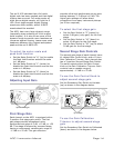
Locking to an External Clock
Source
The ADC1 can sync to a variety of external
clock sources, including Word Clock, Super
Clock, AES, and SPDIF. Once the ADC1
acquires sync, it will perform conversion at
the sample rate of the external clock.