


ADC1 Instruction Manual Page 12
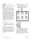
Off = Internal Sync
On = Locked to External Sync
Flash = External Sync Selected
but Not Locked
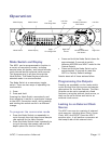
The bottom left LED in the Mode Display is
the Ext Indicator. It shows that the ADC1 is
locked to an external clock source. If the Ext
LED is off, then the ADC1 is set to operate at
a fixed sample rate using the internal clock
source. If the Ext LED is on, the ADC1 is
locked to an external clock. When locked, the
Mode Display will indicate the sample rate.
The ADC1 will automatically switch sample
rates in response to changes in the reference
sample rate. If the Ext LED is flashing, then
the ADC1 is set to sync to an external clock
source, but the ADC1 has not acquired a lock.
The ADC1 should lock in less than 5 seconds.
If the Ext LED flashes for more than 5
seconds, there is something wrong with the
clock reference. Check the connections to the
ADC1 Ref Input. The ADC1 will lock to AES,
SPDIF, WC, or Super Clock and is very
tolerant of low-level low-quality reference
signals.
To synchronize with an external
clock source
• Press up repeatedly on the Mode Switch,
cycling through the Main Output modes
until the lower left Ext LED is either on or
flashing.
Selecting a Fixed Frequency
Using the Internal Clock Source
The ADC1 can be programmed to convert at a
fixed frequency using an internal clock
source. The following sample rate frequencies
are available: 44.1, 48, 88.2, 96, 176.4, and
192 kHz. The ADC1 External Clock Input is
ignored when the internal clock source is
selected.
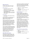
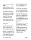
To select a fixed sample frequency
on the Main Outputs
• Press up repeatedly on the Mode Switch to
cycle through the available sample
frequencies until the four LEDs in the
upper left of the Mode Display match one
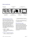
of the diagrams below.
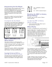
Black = Lit
White = Not Lit
Gray = Irrelevant
44.1kHz 48 kHz 88.2 kHz
96 kHz 176.4 kHz 192 kHz
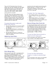
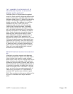
Reading Sample Rates off of the
Mode Display
Column one of the display has a “44” LED and
a “48” LED. These indicate sample rates of
44.1 kHz and 48 kHz respectively. Column
two has an “X2” LED and an “X4” LED. These
indicate 2x or 4x multipliers. Multiply the
sample rate shown in column one by the
multiplier shown in column two. For example,
if the 44 and X2 LEDs are on, the sample rate
is 88.2 kHz (44.1 x 2 = 88.2).