


ADC1 Instruction Manual Page 7
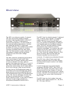
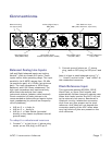
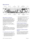
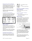
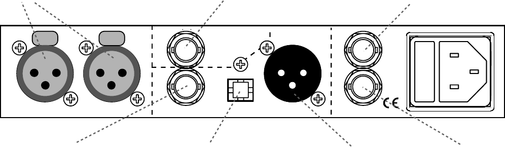
Connections
Main 24-Bit Digital Outputs
Aux 24 or 16-Bit
Digital Output
Analog Line In
AES/EBU
ADAT/SPDIF
SPDIF,
AES
WC
Out
AES,
WC,
SC
Ref In
Left Right
Balanced Analog
Line Inputs (XLR)
Auxiliary Digital Output,
BNC (AES)
Clock Reference Input,
BNC (AES, Wordclock, Superclock)
Wordclock Reference
Out
p
ut, BNC
Main Digital Output,
XLR (AES /EBU)
Main Digital Output,
TOSLINK O
p
tical (ADAT /SPDIF)
Main Digital Output,
BNC (SPDIF/AES)
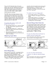
Balanced Analog Line Inputs
Left and Right balanced inputs use locking
Neutrik™ gold-pin female XLR jacks. These
inputs have a wide operating range. The input
sensitivity (at 0 dBFS) ranges from -20 dBu
(at maximum gain) to +29 dBu (at minimum
gain). The input impedance is 200k Ohms
balanced, and 100k Ohms unbalanced. The
high input impedance and input sensitivity,
allow direct connections from many
instrument pickups (adapter cable required).
Direct connection of piezo pickups is not
recommended as these pickups require higher
input impedances (to prevent low-frequency
roll-off problems).
• XLR pin 2 = + Audio In
• XLR pin 3 = - Audio In
• XLR pin 1 = Cable Shield (grounded
directly to the chassis to prevent internal
ground loops)
To adapt to unbalanced sources
1. Connect “+” or hot (tip on ¼ phone plug,
center pin on RCA plug) to XLR pin 2.
2. Connect ground (sleeve on ¼” phone
plug, case on RCA plug) to XLR pins 3 and
1.
Note it is best to used balanced wiring (“+”,
“-“, “shield”) and to tie the “-“and “shield” at
the unbalanced connector.
Clock Reference Input
This input auto-detects AES/EBU, SPDIF,
Word Clock, or Super Clock signals, and
automatically follows changes in sample-rate.
When Auto mode is active the ADC1 will lock
to the external clock source. Benchmark’s
UltraLock circuitry isolates the conversion
clock from any jitter present on the clock
reference. Auto Mode will not degrade the
conversion quality of the ADC1 even when
very high levels of jitter are present on the
clock reference.