ADC1 Instruction Manual Page 3
Contents
Overview 4
Features 6
Connections 7
Balanced Analog Line Inputs 7
Clock Reference Input 7
Digital Outputs 8
AES/EBU XLR Output 8
Optical Output 8
SPDIF/AES BNC Main and Aux Outputs 9
Word Clock Reference Output 10
AC Power Entry Connector 10
Fuse Holder 10
Operation 11
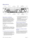
Mode Switch and Display 11
Programming the Outputs 11
Locking to an External Clock Source 11
Selecting a Fixed Frequency Using the
Internal Clock Source 12
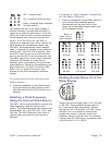
Reading Sample Rates off of the Mode
Display 12
Programming the Aux Output 12
ADAT or AES/EBU on the Optical Output 13
Resetting the ADC1 to Factory Default
Settings 13
Meter Display 13
Adjusting Input Gain 14
First Stage Gain 14
Second Stage Gain Controls 14
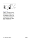
Rack Mounting 15
Using ADAT S/MUX 16
UltraLock™ … What is It? 17
Performance 20
Frequency Response 20
Inter-Channel Phase Response 21
THD+N vs. Level, 1 KHz 22
32K B-H FFT, Idle Channel Noise 23
32K B-H FFT, -3 dBFS, 1 KHz 24
32K B-H FFT, -3 dBFS, 10 KHz 25
Specifications 26
Analog Audio Inputs 26
Clock Reference Input 26
Worldclock Reference Output 26
Digital Audio Outputs 27
Audio Performance 28
Group Delay (Latency) 29
LED Status Indicators 29
AC Power Requirements 30
Dimensions 30
Certificate of Compliance 31
Warranty 32
Extended Warranty 33
Copyright and Contact Information 34


