


36 Chapter 1
Making Basic Measurements
Measuring Low Level Signals
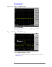
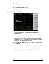
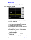
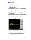
12.To see the signal more clearly, enter 0 dB. Zero decibels of
attenuation makes the signal more visible. See Figure 1-28.
Figure 1-28 Using 0 dB Attenuation
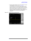
CAUTION Before connecting other signals to the analyzer input, increase the RF
attenuation to protect the analyzer input: press
Attenuation so that Auto
is underlined or press Auto Couple.
Measuring Low Level Signals Example 2:
The resolution bandwidth can be decreased to view low level signals.
1. Connect a signal generator to the analyzer input.
2. Set the signal generator frequency to 300 MHz with an amplitude of
−80 dBm.
3. On the analyzer, perform a factory preset by pressing Preset,
Factory Preset (if present).
4. Set the center frequency of the analyzer to 300 MHz by pressing
FREQUENCY, Center Freq, 300, MHz.
5. Set the span to 5 MHz by pressing SPAN, Span, 5, MHz.
6. Set the resolution bandwidth to spectrum analyzer coupling by
pressing
BW/Avg, Res BW (SA).
7. Set the Y-Axis Units to dBm by pressing AMPLITUDE, More,
Y-Axis Units,
dBm.
8. Set the reference level to −40 dBm by pressing AMPLITUDE, Ref Level,
–40, dBm.