


Chapter 2 75
Making Complex Measurements
Making Stimulus Response Measurements
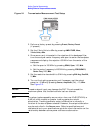
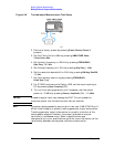
12.Reconnect the DUT to the analyzer. Note that the units of the
reference level have changed to dB, indicating that this is now a
relative measurement.
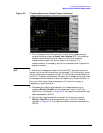
Press
Trace/View, More, Normalize, Norm Ref Posn to change the
normalized reference position. Arrowheads at the left and right
edges of the graticule mark the normalized reference position, or the
position where 0 dB insertion loss (transmission measurements) or
0 dB return loss (reflection measurements) will normally reside.
Using the knob results in a change in the position of the normalized
trace, within the range of the graticule.
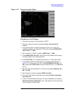
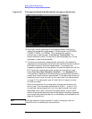
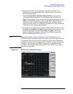
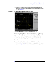
13.To measure the rejection of the filter 45 MHz above the center of the
bandpass, press
Marker, 200, MHz (to ensure that the marker is in the
center of the signal), and then press
Delta, 45, MHz. The marker
readout displays the rejection of the filter at 45 MHz above the
center of the bandpass. See Figure 2-4.
NOTE Because the default trace is comprised of 401 discrete points, the
indicated marker frequency may differ slightly from the frequency that
you entered. Due to the horizontal resolution of the trace, the marker
frequency value will be rounded to within 0.25% of the span of the value
entered. If the analyzer is an ESA-E series with firmware revision
A.04.00 or later, the number of sweep points may be set to any value
between 101 and 8192.
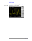
Figure 2-4 Measure the Rejection Range