


12 Chapter 1
Making Basic Measurements
Comparing Signals
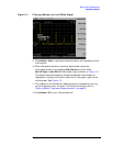
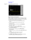
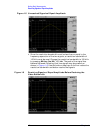
Figure 1-2 Using the Marker Delta Function
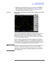
Signal Comparison Example 2:
Measure the frequency and amplitude difference between two signals
that do not appear on the screen at one time. (This technique is useful
for harmonic distortion tests when narrow span and narrow bandwidth
are necessary to measure the low level harmonics.)
1. Perform a factory preset by pressing Preset, Factory Preset (if
present).
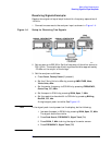
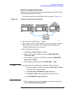
2. Connect the 10 MHz REF OUT from the rear panel to the
front-panel INPUT.
3. Set the center frequency to 10 MHz by pressing FREQUENCY,
Center Freq, 10, MHz.
4. Set the span to 5 MHz by pressing SPAN, 5, MHz.
5. Set the resolution bandwidth to spectrum analyzer coupling by
pressing BW/Avg, Res BW (SA).
6. Set the Y-Axis Units to dBm by pressing AMPLITUDE, More,
Y-Axis Units,
dBm.
7. Set the reference level to 10 dBm by pressing AMPLITUDE, Ref Level,
10, dBm.
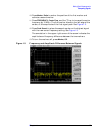
The 10 MHz reference signal appears on the display.
8. Press Peak Search to place a marker on the peak.
9. Press Marker→, Mkr→CF Step to set the center frequency step size
equal to the frequency of the fundamental signal.