


42 Chapter 1
Making Basic Measurements
Identifying Distortion Products
Identifying Distortion Products
Distortion from the Analyzer
High level input signals may cause analyzer distortion products that
could mask the real distortion measured on the input signal. Using
trace 2 and the RF attenuator, you can determine which signals, if any,
are internally generated distortion products.
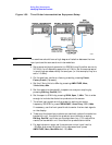
Identifying Analyzer Generated Distortion Example:
Using a signal from a signal generator, determine whether the
harmonic distortion products are generated by the analyzer.
1. Connect a signal generator to the analyzer INPUT.
2. Set the signal generator frequency to 200 MHz and the amplitude to
0dBm.
3. On the analyzer, perform a factory preset by pressing Preset,
Factory Preset (if present).
4. Set the Y-Axis Units to dBm by pressing AMPLITUDE, More,
Y-Axis Units,
dBm.
5. Set the resolution bandwidth to spectrum analyzer coupling by
pressing
BW/Avg, Res BW (SA).
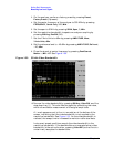
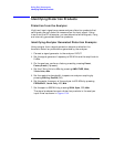
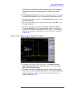
6. Set the center frequency of the analyzer to 400 MHz by pressing
FREQUENCY, Center Freq, 400, MHz.
7. Set the span to 500 MHz by pressing SPAN, Span, 500, MHz.
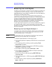
The signal produces harmonic distortion products in the analyzer
input mixer as shown in Figure 1-34.