


72 Chapter 2
Making Complex Measurements
Making Stimulus Response Measurements
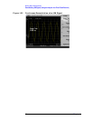
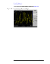
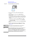
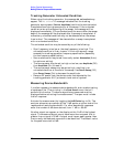
Figure 2-1 Transmission Measurement Test Setup
2. Perform a factory preset by pressing
Preset, Factory Preset
(if present).
3. Set the Y-Axis Units to dBm by pressing
AMPLITUDE, More,
Y-Axis Units,
dBm.
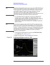
4. Since we are only interested in the rejection of the bandpass filter,
tune the analyzer center frequency and span to center the bandpass
response and display the rejection ±50 MHz from the center of the
bandpass.
a. Set the span to 100 MHz by pressing
SPAN, Span, 100, MHz.
b. Set the center frequency to 200 MHz by pressing
FREQUENCY,
Center Freq, 200, MHz.
5. Set the resolution bandwidth to 3 MHz by pressing
BW/Avg, Res BW,
3, MHz.
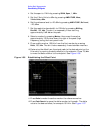
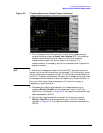
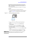
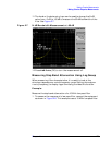
6. Turn on the tracking generator and if necessary, set the output
power to –10 dBm by pressing
Source, Amplitude (On), –10, dBm.
See Figure 2-2.
CAUTION Excessive signal input may damage the DUT. Do not exceed the
maximum power that the device under test can tolerate.
NOTE To reduce ripples caused by source return loss, use 10 dB (E7401A) or
8 dB (all other models) or greater tracking generator output
attenuation. Tracking generator output attenuation is normally a
function of the source power selected. However, the output attenuation
may be controlled in the
Source menu. Refer to specifications and
characteristics in your specifications guide for more information on the
relationship between source power and source attenuation.