


HSC-ADC-EVALC
Rev. 0 | Page 4 of 32
EVALUATION BOARD HARDWARE
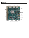
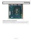
HSC-ADC-EVALC ADC CAPTURE BOARD
EASY START
Requirements
• HSC-ADC-EVALC ADC capture board, VisualAnalog, 5 V
wall transformer, and USB cable
• High speed ADC evaluation board and ADC data sheet
• Power supply for ADC evaluation board
• Analog signal source and appropriate filtering
• Low jitter clock source applicable for specific ADC
evaluation, typically <1 ps rms jitter
• PC running Windows® 98 (2nd edition), Windows 2000,
Windows ME, or Windows XP
• PC with a USB 2.0 port recommended (USB 1.1 compatible)
Easy Start Steps
Important Note
Administrative rights for the Windows operating systems are
needed during the entire easy start procedure.
Completion of every step before reverting to a normal user
mode is recommended.
1. Install VisualAnalog from the CD provided in the ADC
capture board kit or download the latest version from the
Web. For the latest updates to the software, check the
Analog Devices website at
www.analog.com/FIFO.
2. Connect the ADC capture board to the ADC evaluation
board. If an adapter is required, insert the adapter between
the ADC evaluation board and the ADC capture board.
3. Connect the provided USB cable to the ADC capture board
and to an available USB port on the computer.
4. Refer to
Table 1 for setting the ADC capture board’s I/O
logic level to match the level coming from the ADC evalua-
tion board. 1.8 V is default; 2.5 V and 3.3 V are jumper
selectable. Most evaluation boards can be used with the
default settings.
5. The ADC capture board is supplied with a wall mount
switching power supply. Connect the supply end to an ac
wall outlet rated for 100 Vac to 240 Vac at 47 Hz to 63 Hz.
The other end is a 2.1 mm inner diameter jack that connects
to the PCB at J4.
6. Once the USB cable is connected to both the computer and
the HSC-ADC-EVALC board, and power is applied, the
USB driver starts to install. The Found New Hardware
Wizard opens and prompts you through the automated
install process.
7. (Optional) Verify in the Windows device manager that
Analog Devices ADC-HSC-EVALC is listed under the
USB hardware.
8. Refer to the instructions included in the respective ADC
data sheet found at
www.analog.com/FIFO for more
information about connecting the ADC evaluation board’s
power supply and other requirements. After verification of
power supply connections, apply power to the ADC
evaluation board and check the voltage levels on the ADC
board to make sure they are correct.
9. Make sure the evaluation boards are powered on before
connecting the analog input and clock. Connect the
appropriate analog input (which should be filtered with a
band-pass filter) and low jitter clock signal.
10. Refer to the VisualAnalog User Manual at
www.analog.com/FIFO for detailed software operating
instructions.
POWER SUPPLIES
The ADC capture board is supplied with a wall mount switch-
ing power supply that provides a 5 V, 3 A maximum output.
Connect the supply to the rated 100 Vac to 240 Vac wall outlet at
47 Hz to 63 Hz. The other end is a 2.1 mm inner diameter jack
that connects to the PCB at J4. On the PC board, the supply is
fused and conditioned before connecting to the regulators that
supply the proper bias to the entire ADC capture board.
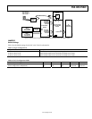
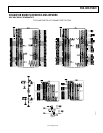
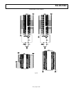
CONNECTION AND SETUP
The ADC capture board has two 40-pin connectors (J2 and J3)
that accept two 18-bit channels of parallel CMOS or LVDS
inputs from the ADC (see
Figure 2). The third 40-pin connector
(J1) is used to pass SPI and other USB/FPGA control signals
across to adjacent ADC evaluation boards that support these
features.