


IMPORTANT!!!
INST
ALLATION OF THIS PRODUCT SHOULD BE PERFORMED ONLY BY A PROFESSIONAL INSTALLER AND
IS NOT RECOMMENDED FOR CONSUMER D.I.Y. (DO-IT-YOURSELF) INSTALLATIONS.
DANGER!!!
WATCH FOR WIRES! YOU CAN BE KILLED IF THIS PRODUCT COMES NEAR POWER LINES. Installation of this product near power lines is dan-
gerous. For your own safety, follow these important safety rules.
1. Perform as many functions as possible on the ground.
2. Watch out for overhead power lines. Check the distance to the power lines before starting installation.
We recommend you stay a minimum of 6 meters (20 feet) from all power lines.
3.
Do not use metal ladders.
4. Do not install antenna or mast assembly on a windy day.
5. If you start to drop antenna or mast assembly, get away from it and let it fall.
6. If any part of the antenna or mast assembly comes in contact with a power line, call your local power company.
DO NOT TRY TO REMOVE IT YOURSELF! They will remove it safely.
7. Make sure that the mast assembly is properly grounded.
WARNING!!!
Assembling dish antennas on wind
y days can be dangerous. Because of the antenna surface, even slight winds create strong forces. For
example, a 1.0m antenna facing a wind of 32 km/h (20 mph) can undergo forces of 269 N (60 lbs). Be prepared to safely handle these forces at
unexpected moments. Do not attempt to assemble, move or mount a dish on windy days or serious, even fatal accidents may occur.
Andrew Corporation
®
is not responsible or liable for damage or injury resulting from antenna installations.
Antennas improperly installed or installed to an inadequate structure are very susceptible to wind damage. This damage can be very serious or even
life threatening. The owner and installer assumes full responsibility that the installation is structurally sound to support all loads (weight, wind & ice)
and properly sealed against leaks. Andrew will not accept liability for any damage caused by a satellite system due to the many unknown variable
applications.
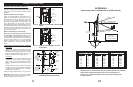
The first and most important consideration when
choosing a prospectiv
e antenna site is whether or not the
area can provide an acceptable “look angle” at the
satellites. A site with a clear, unobstructed view is preferred.
Also consider obstr
uction that may occur in the future such
as the g
rowth of trees.Your antenna site must be selected in
advance so that you will be able to receive the strongest
signal a
vailable. To avoid microwave interference, obstruc-
tions, etc. conduct an on-site survey with a portable antenna.
As with any other type of construction, a local building
permit may be required before installing an antenna. It is the
property owner’s responsibility to obtain any and all permits.
Before any digging is done, information regarding the possi-
bility of underg
round telephone lines, power lines, storm
drains, etc. in the excavation area should be obtained from
the appropriate agency.
Because soils vary widely in composition and load capacity,
consult a local prof
essional engineer to deter
mine the
appropriate foundation design and installation procedure. A
suggested foundation design with conditions noted is included
in this manual for reference purposes only.
2
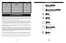
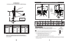
ASSEMBLY TOOLS REQUIRED
1 - Compass 1 - 10mm Nut Driver 1 - 13mm Deep Socket (³⁄₈” Drive)
1 - Clinometer 1 - 10mm Socket (
³⁄₈” Drive) 1 - 9” Magnetic Level
1 - Ratchet Wrench (
³⁄₈” Drive) 1 - Phillips Screwdriver (#1 or #2) 1 - 13mm Combination Wrench
1- Torque Wrench 1 - 10mm Combination Wrench
PREINSTALLATION MATERIALS CHECKLIST
Grounding Rod Clamp & Grounding Bloc
k - As Required b
y National Electr
ic Code or local codes
.
Ground Wire - #10 solid copper as or required by National Electric Code or local codes (length required).
Concrete - (See Ground Pole section for quantity and grade).
#3 Rebar - (See Ground P
ole section f
or quantity).
Deformed steel per ASTM A615, grade 40 or 60.
SITE SELECTION
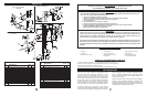
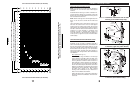
QTY.
NO
.
DESCRIPTION
96cm
1.2m
1 BOLT, PLOW, SPECIAL, M8 x 1.25 x 56 mm 2 -
BOLT, PLOW, SPECIAL, M8 x 1.25 x 91 mm 2 4
2 REFLECTOR, .96m 1 1
REFLECTOR, 1.2m LFL 1 1
3 BOLT, HEX HD, SS, M6 x 1.0 x 20mm 4 4
4 WASHER, LOCK, SS, M8 4 4
5 NUT, HEX HD M8 x 1.25 4 4
6 BOLT, RD HD SQ NK M6 x 1.0 x 22mm 1 5
7 PLATE, EXTENSION - 1
8 WASHER, LOCK, SS, M6 (Light Duty) 5 5
WASHER, LOCK, SS, M6 (Medium Duty) 7 9
9 NUT, HEX HD, M6 x 1.0 (Light Duty) 3 3
NUT, HEX HD, M6 x 1.0 (Medium Duty) 5 7
10 BRACE, R.H. .96m AZ/EL MT 1 -
BRACE, 1.2m LFL AZ/EL (Medium Duty) - 2
11 BRACE, L.H. .96m AZ/EL MT 1 -
12 WASHER, EXT
T
OO
TH LOCK, M6
2
2
15
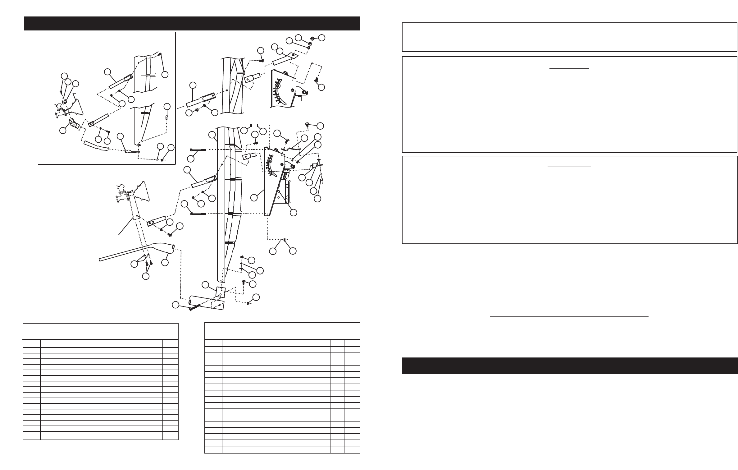
PARTS LIST
CLASS I - LIGHT DUTY SYSTEM
(1.2m SHOWN)
C
LASS II - MEDIUM DUTY SYSTEM
(1.2m SHOWN)
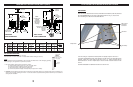
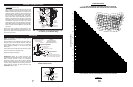
96cm CLASS II - MEDIUM DUTY
F
EED
ASSEMBLY
FEED
ASSEMBLY
2
5
2
4
23
2
0
3
9
2
1
20
8
9
1
8
19
18
18
16
15
6
13
8
9
4
5
9
13
12
10
9
8
6
7
6
4
3
5
14
19
8
2
0
3
10
11
1
2
1
3
9
6
1
5
8
3
8
21
19
8
2
2
9
9
26
QTY
.
NO. DESCRIPTION 96cm 1.2m
13
W
ASHER, FLA
T
, SS, M6 (Medium Duty) 3 3
14
MOUNT ASSEMBLY, 1.2m LFL (Light Duty) 1 1
15 NUT, M6 x 1.0, ESNA 1 1
16
“U”
CUP
, BOOM
-
1
17 BOLT, RD HD SQ NK, M6 x 1.0 x 55mm 1 1
18 FEED SUPPORT (Medium Duty) 1 -
FEED SUPPORT (Medium Duty) - 1
19 BOLT, HEX HD, SS, M6 x 1.0 x 16mm (Light Duty) 3 3
BOLT, HEX HD, SS, M6 x 1.0 x 16mm (Medium Duty) 4 4
20
SIDE FEED LEG, .96m ANTENNA
2
-
SIDE FEED LEG, 1.2m, ANTENNA - 2
21 BOTTOM FEED LEG (.96m Light Duty) 1 -
BO
TT
OM FEED LEG (1.2m Light Duty)
-
1
22
TERMINAL, FEED SUPPOR
T (Light Duty)
1
1
23 CLAMP, MTG BLOCK (Light Duty) 1 1
24 WASHER, FLAT M6 (Light Duty) 2 2
25 BOLT, HEX HD, M6 x 1.0 x 30mm 2 2
26 BOLT, HEX HD, M8 x 1.25 X 20mm 2 2