


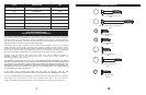
0 10 20 30 40 50 60 70 80
0
20
40
60
80
10
30
50
70
90
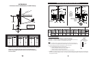
ANTENNA
FEED
NORTHERN SOUTHERN
POLARIZATION CHART SIGN VALUES (+ OR -) HEMISPHERE HEMISPHERE
ANTENNA SITE WEST OF SATELLITE LONGITUDE - +
ANTENNA SITE EAST OF SATELLITE LONGITUDE + -
EARTH STATION LATITUDE IN DEGREES NORTH OR SOUTH OF EQUATOR
POLARIZATION + OR — (SEE ILLUSTRATION)
" L" IS THE DIFFERENCE BETWEEN THE EARTH STATION
ANTENNA SITE LONGITUDE AND THE SATELLITE LONGITUDE
POLARIZATION CHART
+—
CHART 1
75
O
60
O
40
O
30
O
20
O
15
O
10
O
5
O
Feed Rotation (Facing Antenna)
For + Polarization, Rotate CCW (Counter Clockwise)
For - Polarization, Rotate CW (Clockwise)
9
8
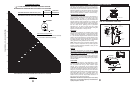
Alignment with the satellite is obtained by setting polariza-
tion, elevation and azimuth. Charts 1, 2 & 3 are to determine
these values for your earth station antenna site. “∆L” is the
difference between the earth station antenna site longitude
and the satellite longitude. Use “∆L” and your earth station
latitude to obtain polarization, elevation or azimuth setting.
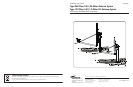
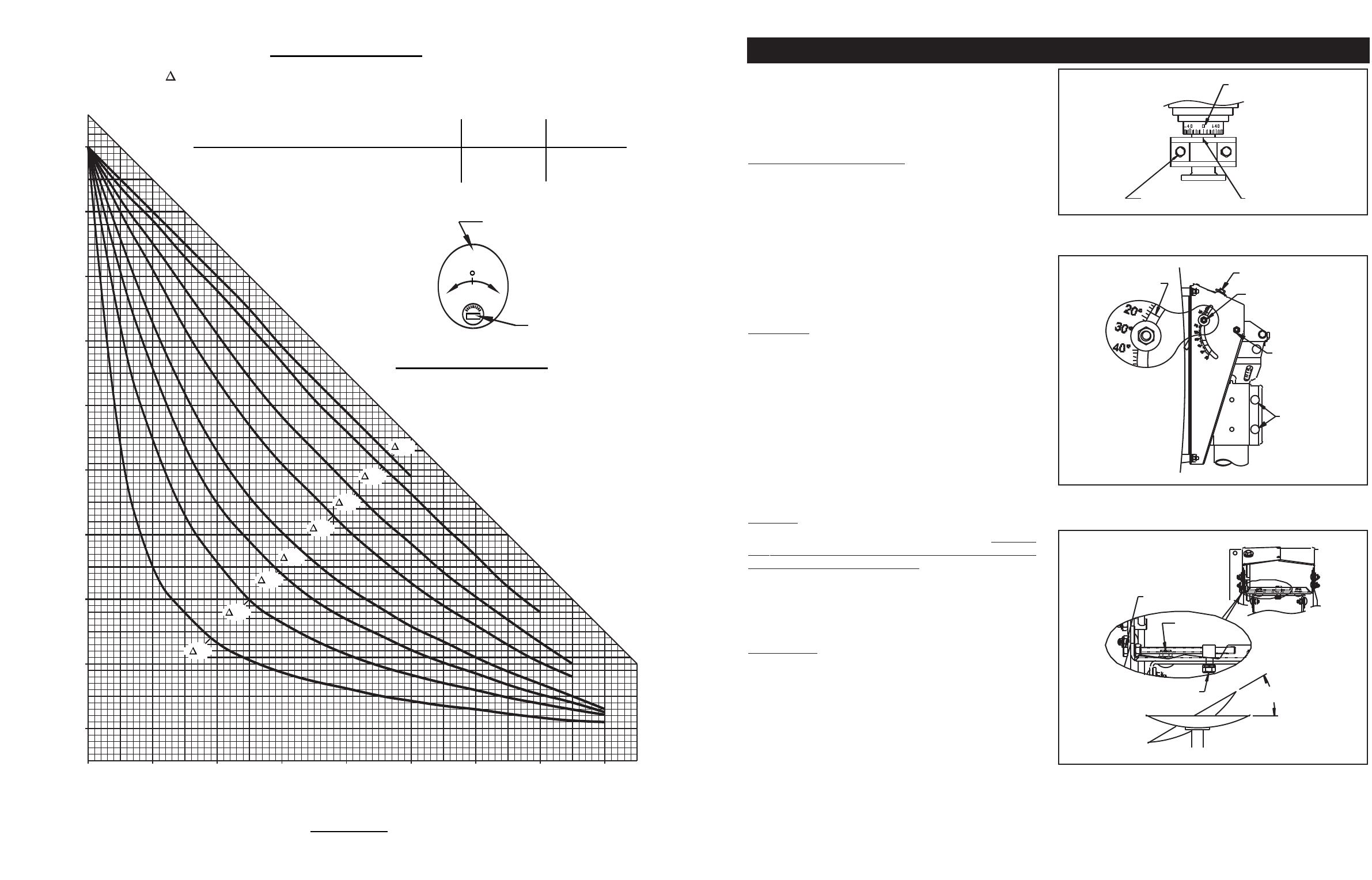
POLARIZATION OF THE FEED
Loosen Feed Horn Clamp Bolts and turn Feed clockwise or
counterclockwise, depending on being east or west of the
satellite as shown on Chart 1. For course setting, align
marks on the Horn Scale (Ref. Fig. 3.0). Polarization chart
assumes antenna system polarization is Tx vertical and
satellite vertical Pol is perpendicular to plane of geostation-
ary arc. For horizontal Tx of antenna, Feed must be rotated
90˚ from values shown. (Starting point for polarization
adjustment is 0˚, as shown in Figure 3.0.) Use a signal
strength measur
ing device for final polarization setting and
tighten horn clamp bolts to 4 ft-lbs (5.4 N-m).
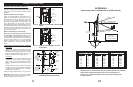
ELEVATION
Use Chart 2 and determine your elevation setting. Loosen
Elevation Pivot Bolts and Bolts in curved slots (both sides)
of AZ/EL housing approximately 1 complete turn (Ref. Fig.
3.1). Turn Elevation Adjustment Bolt clockwise to decrease
elevation and counterclockwise to increase elevation. Align
the edge of the Clamp with appropriate mark on housing at
the desired elevation reading. This will be an approximate
setting. Optimum setting achieved when fine tuning.
NOTE: Degree values shown on Elevation Scale are Beam;
there is no need to compensate for any offset angle. (See
Appendix A, Outline Drawing).If clinometer is used, you must
compensate for offset angle.
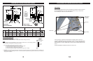
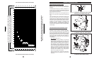
AZIMUTH
Use Chart 3 and determine your azimuth setting. Values in
chart must be adjusted for magnetic deviation for your loca-
tion for correct compass reading. Rotate Reflector and
Mount pointing it to the correct compass reading. Slowly
sweep the antenna in azimuth until signal is found. If the
desired signal is not f
ound, increase or decrease ele
v
ation
setting and repeat the azimuth sweep (Ref. Fig. 3.2). Tighten
Half Clamp Bolts .
FINE TUNING
Use Signal Tuning Device for final adjustments to obtain
maxim
um antenna perf
or
mance
. Alternate between eleva-
tion and azimuth fine tuning to reach maximum signal
strength, until no improvement can be detected. Certain
models utiliz
e the optional azim
uth fine tune f
eature (ref
er to
Figure 3.2). This allows the azimuth to be fine tuned by loos-
ening the (4) Carriage Head Bolts and Swivel Nut which
allo
ws adjusting the Azim
uth Fine
T
une Adjusting Bolt f
or the
peak signal. When fine tuning is complete, tighten and
torque all AZ/EL hardw
are to 12 ft-lbs (16.3 N-m).
Do not
exceed 12 ft-lbs (16.3 N-m). Torque Clamp Hardware to 18
ft-lbs (24.4 N-m) in alternating sequence.
IMPORTANT: Recheck and repeat torque on four Clamp
Bolts, Fig. 3.1 in alternating sequence, until all Bolts are
equally torqued to 18 ft-lbs.
FIG. 3.0 - Polarization of the Feed
HORN SCALE
ALIGNMENT MARK
CLAMP BOLT
FIG. 3.1 - Setting the Elevation
EDGE OF CLAMP
BRACKET
EXAMPLE:
18" ELEVATION
ELEVATION ADJUSTING
SCREW
CURVED SLOT BOLT
ELEVATION
PIVOT
BOLT
CLAMP BOLT
(
4 PLCS)
FIG. 3.2 - Rotating Antenna for Azimuth
AZIMUTH FINE TUNE
ADJUSTING BOLT
HEX NUT,
CARRIAGE BOLT (4)
HEX NUT,
SWIVEL NUT
AZIMUTH
ANTENNA ALIGNMENT PROCEDURE