


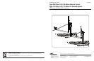
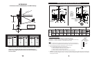
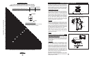
GROUND POLE INSTALLATION (96cm System)
M
IN.
D
IA.
d
d
MIN.
DIA.
ANT
2.88" or
3.00" O.D.
2.88" or
3.00" O.D.
40"
C
L
72"
36.4"
36.4"
i
ncreased,
72"
41.5"
5
0" depth may be
w
ill increase
l
ength of rebar
c
oncrete and
accordingly.
2"
2"
50"
NOTE:
#3 REBAR x DIA. OF PIER, INSERT
FROST LINE
#3 REBAR x
DIA. OF PIER
INSERT THRU HOLE
IN TUBE & CENTER
AT 90
o
APART
(SEE NOTE)
(4)#3x24"MIN.
BELOW
THRU HOLE IN TUBE & CENTER
1" to 2"
WATER RUN OFF
GRADE
SLOPE FOR
BELOW
FROST LINE
APPROX.
1" to 2"
SLOPE FOR
(SEE
NOTE)
GRADE
WATER RUN OFF
GROUND
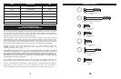
ANT WIND VEL. DIM “d” CONC VOL. DIM “d” CONC VOL. DIM “d’ CONC VOL. DIM “d” CONC VOL. POLE
80 MPH 7” 0.9 10” 1.8 7” 1.2 7” 1.2 “A”
90 MPH 8” 1.2 13” 3.0 7” 1.2 8” 1.5
96cm 100 MPH 10” 1.8 15” 4.0 7” 1.2 10” 2.4 “A” or
110 MPH 11” 2.2 17” 5.2 7” 1.2 11” 2.9 “B”
125 MPH
14”
3.5 20” 7.2 9” 1.9 14” 4.7 “B” Only
POLE SPECIFICATIONS:
Ground P
ole
“A”
= 3.00 O
.D. x 10 G.A. x 72” Steel
Ground Pole “B” = 2
⁷⁄₈ O.D. x .203 Wall x 72” Steel ASTM 120 Mech Tubing (2¹⁄₂ Sch. 40)
NOTE:
Pole not supplied and must be field drilled ⁵⁄₈” dia. for #3 rebar and drilled .218 for ¹⁄₄-20 self tapping grounding
scre
w (see P
age 7) and galv
aniz
ed or painted f
or protection.
1 - P
ole and foundation design based on the following criteria:
a) Uniform building code exposure B or C and 1.5 stability factor.
b) Vertical soil pressure of 2000 pounds per square foot.
c)
Later
al soil pressure of 400 pounds per square f
oot.
d)
Concrete compressive strength of 2500 pounds per square inch in 28 days.
2 -
CAUTION - The foundation design shown does not represent an appropriate design for any specific locality since soil conditions vary
and may not meet design cr
iter
ia giv
en in Note 1.You should consult a local professional engineer to determine your soil conditions
and appropriate f
oundation.
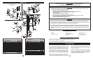
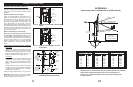
Exposure “B” Exposure “C” Exposure “B” Exposure “C”
PIER FOUNDATIONS DEEP FROST LINE FOUNDATIONS
Bubble
Level
Ground Pole
Must Be
Vertical In
All Directions
Within .19 Inches
At Top (0.3ß)
STANDARD
PIER FOUNDATION
DEEP FROST
LINE FOUNDATION
3
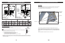
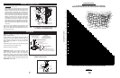
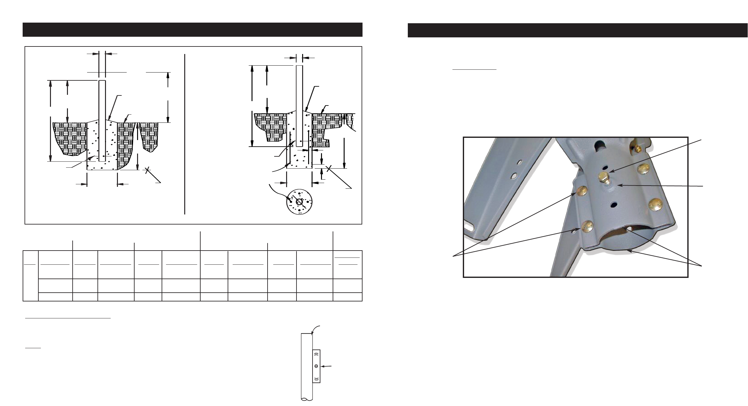
AZ-EL MOUNT WITH M8 INSERT AND SET SCREW
IMPORTANT
M8 x 20 mm Hex Head Set Screws are recommended for schedule 40 (.203 wall) mast and
NOT RECOMMENDED for mast with a wall thickness less than 10 ga (.134) such as
Non-Penetrating Roof Mounts and Roof/Wall Mounts.
Once fine tuning is complete and all Clamp Bolts are equally torqued to 18 ft-lbs. in
accordance with 8000842 manual, then install the two M8 x 20 mm Hex Head Set Screws
supplied. Install one in each clamp half as shown in Fig. 1.0. Torque each M8 x 20 mm
Hex Head Screw to 15 ft-lbs. Repeat torque to insure 15 ft-lbs. has been reached on both
screws.
See Manual 8000842 for additional instructions not shown here.
Clamp Bolts
M8 x 20 mm
Hex Head
Set Screw
M8 Insert
Half Clamp
14
Figure 1.0 (AZ-EL Mount with M8 Insert and Set Screw)