


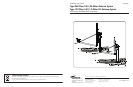
ASSEMBLY AND INSTALLATION
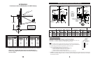
INSTALLING AZ/EL CAP MOUNT ONTO POLE
The AZ/EL Cap is factory preassembled, therefore, no
assemb
ly is required. Before installing AZ/EL Cap onto
ground pole, a concrete foundation should be in place
and cured.
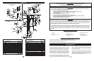
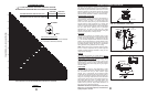
MODEL 611612001 (Fine Tune Option)
Loosen (8) Carriage Bolts and nuts securing the “U”
Bracket to the Top Bracket and “U” Bracket to (2) half
clamps and swivel nut, hex nut (for optional fine tune fea-
ture). (Ref. Fig. 1.0). Install AZ/EL Cap Mount onto
Ground Pole. Equally tighten (4) Clamp Bolts so that
Cap is held stationary on Ground Pole, but can be
swiveled with slight pressure (approximately 2 ft-lbs (2.7
N-m). Retighten and torque (4) Carriage Bolts and nuts
securing “U” bracket to half clamps to 18 ft-lbs (24.4 N-
m). Leave loose (4) Carriage Bolts and Swivel Nut, Hex
Nuts, for fine tune option.
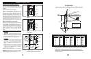
MODEL 611612002 (w/o Fine Tune Option)
Make sure (4) carriage bolts and nuts securing the
(2) Half Clamps to top bracket are loose.
(Ref. Fig.
1.1) Place AZ/EL Cap onto Ground Pole and tighten (4)
Half Clamp Bolts to approximately 2 ft-lbs (2.7 N-m) (just
enough to allow AZ Clamp to turn on pole with slight
pressure). Tighten and torque (4) Carriage Bolts and
Nuts in Top Bracket to 18 ft-lbs (24.4 N-m) (loosened
above).
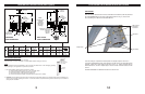
ASSEMBLING REFLECTOR ONTO AZ/EL CAP MOUNT
96cm System
Install two M8 x 56 (56 mm) Plow Bolts into holes in
Reflector Face and two (91 mm) into bottom holes.
Lift Reflector and insert exposed portion of bolt into
holes into Antenna Br
ac
ket Flange. Install 4 Lock
Washers and Hex Nuts on bolts. (Ref. Fig. 1.2)
1.2m System
Install four M8 x 91 (91 mm) Plow Bolts into top holes
in Reflector Face. Lift Reflector and insert exposed
portion of bolt to holes in Antenna Bracket Flange.
Install 4 Lock Washers and Hex Nuts on bolts. (Ref.
Fig.
1.2)
Assemble Extension Plate to AZ/EL Housing using
two M6 x 22mm Round Head Square Neck Bolts,
Lock Washers, and Hex Nuts. (Ref. Fig. 1.3) Tighten
and torque to 6 ft-lbs (8 N-m).
Tighten and torque Reflector bolts to 11 ft-lbs (15 N-m).
IMPORTANT: Note or
ientation of bolt holes in Reflector
Flange. Holes should be located on each side and bot-
tom of the Reflector as shown in Figure 1.2.
T
OP BRACKET
"U" BRACKET
HEX NUT,
CARRIAGE BOLT (8)
H
ALP CLAMP (2)
CLAMP BOLTS
(
CARRIAGE BOLT &
HEX NUT) (4)
HEX NUT
S
WIVEL NUT
FIG. 1.0 - Model 611612001 AZ/EL w/Fine Tune
Option
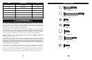
(2 REQ)
PLOW BOLT
M8 x 1.25 x 56
(.96m ONLY)
(2 REQ) .96m
PLOW BOLT
M8 x 1.25 x 91
(QTY. 4, 1.2m)
SIDE BOLT
HOLE
BOTTOM
BOLT
HOLE
GROUND
POLE
CLAMP
BOLTS
HEX NUT
(4 REQ)
LOCK WASHER
(4 REQ)
MOUNT ASSEMBLY
FIG. 1.2 - Assembling Reflector to AZ/EL Mount
and Ground Pole (.96cm Shown)
CLAMP BRACKET
H
EX NUT,
CARRIAGE BOLT (4)
HALF CLAMP (2)
CLAMP BOLTS
(CARRIAGE BOLT &
H
EX NUT (4)
FIG. 1.1 - Model 611612002 AZ/EL w/o Fine
Tune Option
5
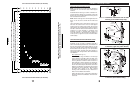
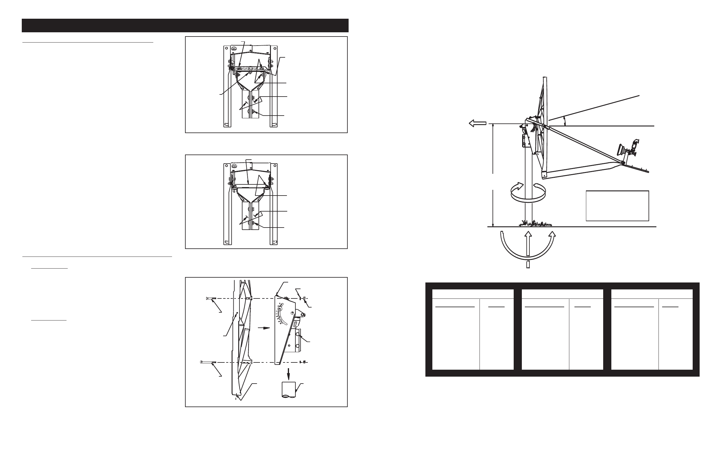
APPENDIX A
96cm Antenna Survival Windloads at 125 MPH Velocity
M
o
Based on 41.5" (1054 mm) from Mounting Surface of Center Line of Antenna
Values shown represent maximum forces for any wind direction and
include 1.5 F
s
. Height and exposure factors from uniform building code
are NOT included.
F
H
= Horizontal Force
F
V
= Vertical Force
M
T
= Torsional Moment
M
O
= Overturning Moment
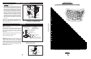
BEAM AXIS
MECHANICAL AXIS
(NORMAL TO ANTENNA FACE)
15.4
o
OFFSET
41.5" HEIGHT
(1054 mm )
F
H
M
T
F
V
M
O
ELEVATION DEGREES
MECHANICAL BEAM
0 15
10 25
20 35
30 45
40 55
50 65
60 75
70 85
FORCE (POUNDS)
F
H
F
V
747 -20
707 -150
687 -289
622 -413
548 -498
478 -548
398 -573
299 -443
MOMENTS (FT-LBS/N-m)
M
T
M
O
150 2584
147 2445
139 2376
126 2151
107 1896
90 1653
70 1377
54 1034
12