


DANGER!!!
WATCH FOR WIRES! Installation of this product near power lines is dangerous. For your own safety, follow these
important safety rules.
1. Perform as many functions as possible on the ground.
2. Watch out for overhead power lines. Check the distance to the power lines before starting installation. We recommend
you stay a minimum of 6 meters (20 feet) from all power lines.
3. Do not use metal ladders.
4. Do not install antenna or mast assembly on a windy day.
5. If you start to drop antenna or mast assembly, get away from it and let it fall.
6. If any part of the antenna or mast assembly comes in contact with a power line, call your local power company.
DO NOT TRY TO REMOVE IT YOURSELF! They will remove it safely.
7. Make sure that the mast assembly is properly grounded.
WARNING!!!
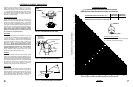
Assembling dish antennas on windy days can be dangerous. Because of the antenna surface, even slight winds
create strong forces. For example, a 1.0m antenna facing a wind of 32 km/h (20 mph) can undergo forces of 269 N
(60 lbs). Be prepared to safely handle these forces at unexpected moments. Do not attempt to assemble, move or
mount a dish on windy days or serious, even fatal accidents may occur. ANDREW is not responsible or liable for dam-
age or injury resulting from antenna installations.
SITE SELECTION
The first and most important consideration when choosing a prospective antenna site is whether or
not the area can provide an acceptable “look angle” at the satellites. A site with a clear, unobstructed view from a suitable
roof or wall facing south, southeast or southwest is required. Your antenna site must be selected in advance so that you
will be able to receive the strongest signal available. To avoid obstructions, it is important to conduct an on-site survey with
a portable antenna.
As with any type of construction, a local permit may be required before installing an antenna. It is the owner’s
responsibility to obtain any and all permits.
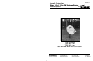
INTRODUCTION
This manual covers the installation of the ANDREW 1.0m &
1.2m SMC antenna system with AZ/EL cap mount and Ku-
single polarity feed.
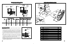
For best results in the assembly process, perform each step
in the same sequence as listed in this manual.
ASSEMBL
Y TOOLS REQUIRED
The following list of tools are those required for hand assembly and installation of the antenna.
1 - Ratchet Wrench (³⁄₈” Drive) 1 - 10mm Nut Driver 1 - 13mm Socket (³⁄₈”Drive)
1 - 13mm Open/Box End Wrench 1 - Phillips Screwdriver 1 - Compass
1
12
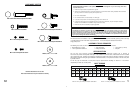
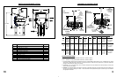
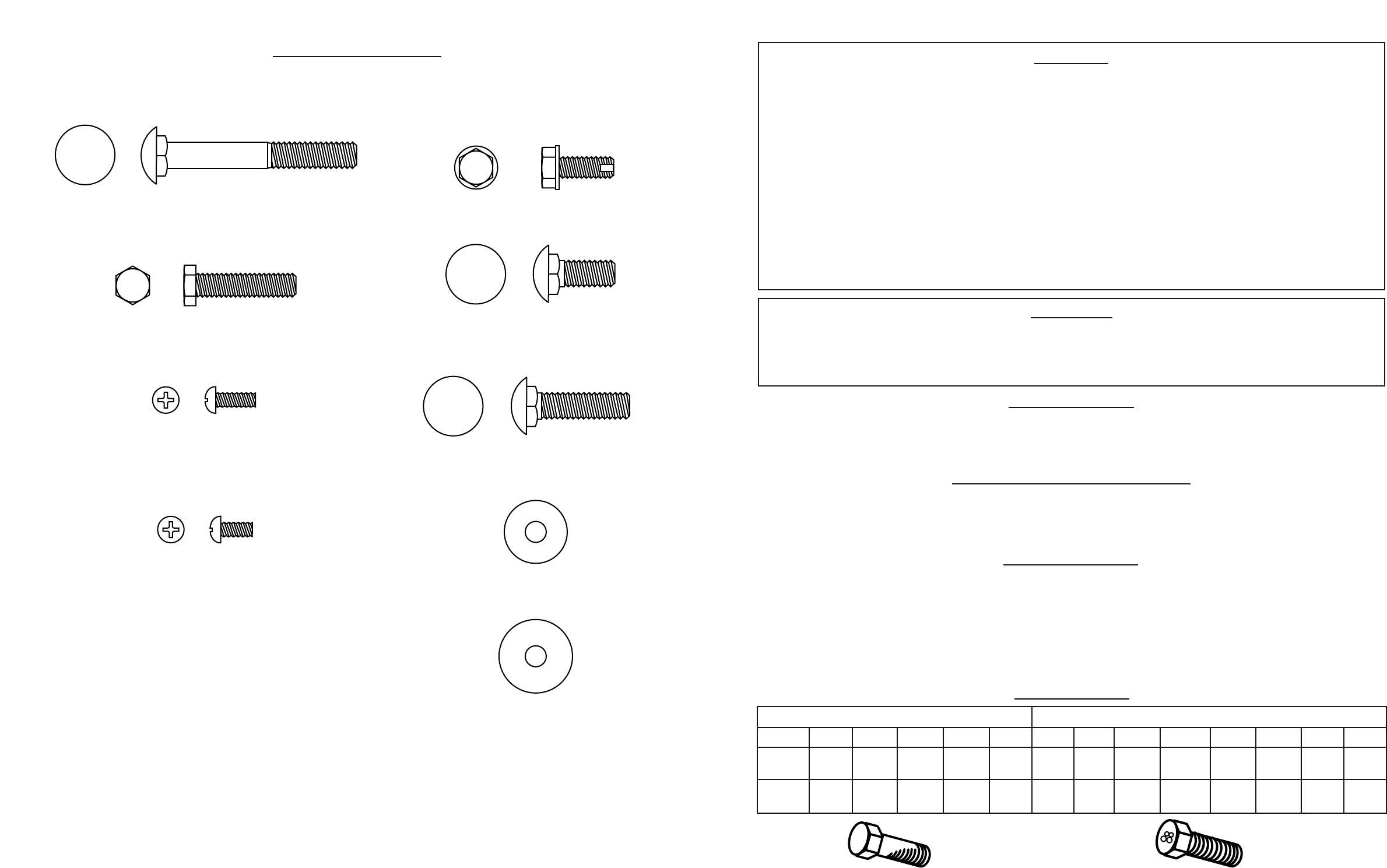
HARDWARE SORTER
GRADE 8.8 (8G) - YELLOW COLOR GRADE 2 - SILVER COLOR
M6 M8 M10 M12 M16 M20 #10 ¹⁄₄ IN. ⁵⁄₁₆ IN. ³⁄₈ IN. ¹⁄₂ IN. ⁵⁄₈ IN. ³⁄₄ IN. 1 IN.
7 18 32 58 144 260 32 6 11 20 43 92 124 259
FT-LBS FT-LBS FT-LBS FT-LBS FT-LBS FT-LBS FT-LBS FT-LBS FT-LBS FT-LBS FT-LBS FT-LBS FT-LBS FT-LBS
9.5 24 43 79 195 353 3.6 8 15 27 58 125 168 351
N-m N-m N-m N-m N-m N-m N-m N-m N-m N-m N-m N-m N-m N-m
APPLY 24 N-m (18 FT-LBS) OF TORQUE TO M8 BOLT
APPLY 11 FT-LBS (15 N-m) OF TORQUE TO ⁵⁄₁₆ BOLT
BOLT TORQUE
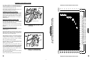
M8 x 60mm Round Head Square Neck Bolt
M4 x 12mm Phillips Head Screw
M8 x 20mm Round Head Square Neck Bolt
M8 x 30mm Round Head Square Neck Bolt
Washer, Flat - ¹⁄₄" x ³⁄₄" OD
Washer, Flat - ¹⁄₄" x ⁷⁄₈" OD
M6 x 30mm Hex Head Bolt
M4 x 10mm Phillips Head Screw
M6 Tapping Screw
Hardware illustrations are true size.
Place actual hardware on top of illustration to identify.