


L
A
d
36
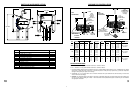
(B)
1" to 2"
SLOPE FOR
WATER RUN OFF
GRADE
#3 REBAR X DIA. OF PIER,
INSERT THRU HOLE IN
TUBE & CENTER
BELOW
FROST LINE
MIN.
DIA.
NOTE:
Clearance
increases at
elevations
greater than 23˚.
3" O.D.
PIER
FOUNDATIONS
L
A
d
48"
(B)
1" to 2"
SLOPE FOR
WATER RUN OFF
GRADE
#3 REBAR
LENGTH = d MIN LESS 1"
INSERT THROUGH
HOLE IN TUBE & CENTER
(4) #3 x 24" MIN.
AT 90˚ APART
(SEE NOTE)
BELOW
FROST LINE
MIN.
DIA.
NOTE:
48" may be
increased, concrete
and length of rebar
will increase
accordingly.
3" O.D.
DEEP
FROST LINE
FOUNDATIONS
(SEE NOTE 2)
1-1.5"
APPROX.
2"
OPTIONAL
10
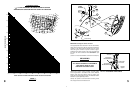
PARTS AND HARDWARE LISTING
8.04 REF
11.80 REF
8.13 REF
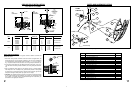
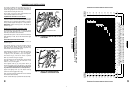
FIG. 4.0 - AZ/EL CAP MOUNT
GROUND POLE INSTALLATION
3” O.D. x 68” & 72” LONG
ANT WIND VEL. DIM “L” DIM “A” DIM “d” CONC VOL. DIM “L” DIM “A” DIM “d” CONC VOL. GROUND POLE
80 MPH 9” 1.5 FT
3
7” 1.2 FT
3
90 MPH 11” 2.2 FT
3
7” 1.2 FT
3
90cm 110 MPH 68” 37” 13” 3.0 FT
3
68” 37” 8” 1.5 FT
3
Mo. 611652731
110 MPH 15” 4.0 FT
3
10” 2.4 FT
3
See Note 2
125 MPH 18” 5.8 FT
3
12” 3.5 FT
3
80 MPH 10” 1.8 FT
3
7” 1.2 FT
3
90 MPH 13” 3.0 FT
3
8” 1.5 FT
3
1.0M 110 MPH 68” 37” 15” 4.0 FT
3
68” 37” 10” 2.4 FT
3
Mo. 611652731
110 MPH 17” 5.2 FT
3
11” 2.9 FT
3
See Note 2
125 MPH 20” 7.2 FT
3
14” 4.7 FT
3
80 MPH 14” 3.5 FT
3
9” 1.9 FT
3
90 MPH 17” 5.2 FT
3
11” 2.9 FT
3
1.2M 110 MPH 72” 39” 19” 6.5 FT
3
72” 39” 13” 4.1 FT
3
Mo. 611685101
110 MPH 22” 8.7 FT
3
15” 5.4 FT
3
See Note 2
125 MPH 25” 11.2 FT
3
19” 8.7 FT
3
PIER FOUND
ATIONS
DEEP FR
OST LINE FOUNDATIONS
POLE SPECIFICATIONS:
3” O.D. x .120 Wall x 68” Long Steel w/Powder Paint Finish - CM PN 611652731.
3” O.D. x .148 Wall x 72” Long Steel w/Powder Paint Finish - CM PN 611685101.
1. Pole and foundation design based on the following criteria: (a) Uniform Building Code Exposure C and 1.5 stability factor, (b) Vertical
soil pressure of 2000 pounds per square foot, (c) Lateral soil pressure of 400 pounds per square foot, (d) Concrete compressive
strength of 2500 pounds per square inch in 28 days.
2. If Model 6851 (3” x 72”) is used for 90cm and 1.0m Antenna Dimension “B” on pier foundation must be increased by 4” and concrete
volume will increase accordingly.
3. CAUTION - The foundation design shown does not represent an appropriate design for any specific locality since soil conditions vary
and may not meet design criteria given in Note 1. You should consult a local professional engineer to determine your soil conditions
and appropriate foundation.
3
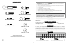
ITEM DESCRIPTION QTY.
1 MOUNT ASSY AZ-EL CAP 2⁷⁄₈”-3” MAST 1
3 CLAMP HALF 2⁷⁄₈”-3” AZ-EL 2
4 HOUSING AZ-EL CAP MOUNT 1
5 BOLT, M8 x 130mm HEX HEAD 1
6 NUT, SWIVEL, SPECIAL M8 1
7 BOLT, M8 x 20mm, CRG 3
8 BOLT, M8 x 30mm, CRG 4
9 WASHER, ⁵⁄₁₆” FLAT 7
10 NUT, M8, HEX 1
11 WASHER, SPHER., DELRIN 1
12 NUT, M8 ELASTIC STOP (ESNA) 8
13 LABEL, ELEVATION ADJUSTMENT 1