


ASSEMBLY AND INSTALLATION
The AZ/EL Cap Mount can be installed on a 2³⁄₈” or 3”
O.D. ground tube, roof, or wall mount depending on
model. The appropriate mount should be assembled and
in place before installing the AZ/EL cap.
As the AZ/EL cap mount is factory preassembled, there
is no assembly required for the mount.
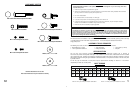
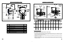
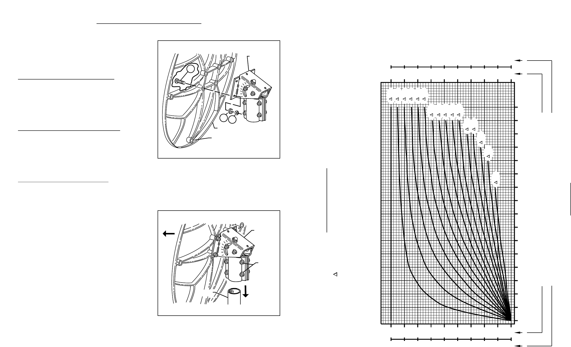
ASSEMBLING ANTENNA TO CAP MOUNT
Install four M8 x 60mm (2³⁄₈”) carriage bolts (1) into holes
in center of reflector and assemble to cap mount flanges.
(Reference Fig. 2.0) Install four lock washers (2) and hex
nuts (3) on bolts.Tighten and torque to 11 ft.-lbs (15 N-m).
IMPORTANT! Bottom feed leg hole to be located as
shown in Fig. 2.0.
INST
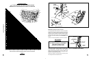
ALLING CAP MOUNT ON MOUNT TUBE
Lift reflector/cap mount assembly and slide cap mount
onto mount tube (Reference Fig. 2.1). Swivel antenna
assembly until reflector faces southward.
Tighten M8 clamp nuts so that the antenna assembly is
held stationary on tube, but can be swiveled with slight
pressure.
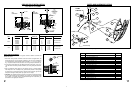
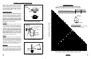
FEED AND FEED LEGS INSTALLATION
Assemble feed assembly and feed legs to antenna as
shown in Fig. 2.2.
Insert bottom feed leg (4) into hole in bottom edge of
antenna (5). NOTE: Bottom feed leg is the one with a
slight bend on one end of leg, lance on opposite end,
and is shorter than the two side legs (6).
Install side legs (6) to antenna. From back side of antenna,
secure with M6 x 30mm (¹⁄₄” x 1³⁄₁₆”) hex bolts and
¹⁄₄” special (⁷⁄₈” O.D.) flat washer (7 & 8). Do not tighten.
Insert bottom leg (4) into hole on center of junction
block* (9) until lance on leg is engaged.
Insert one side leg (6) into junction block* (9) and secure
with M6 x 30mm (¹⁄₄” x 1³⁄₁₆”) hex bolts and ¹⁄₄” flat
washer (7 & 10). Do not tighten.
Insert opposite side leg (6) into junction block* (9)
and secure with M6 x 30mm hex bolt and ¹⁄₄” flat washer
(7 & 10). Tighten and torque bolts securing side legs
to junction block and antenna to 4 ft-lbs (5.4 N-m).
Tighten self tapping screw (31) with bottom feed leg
(make sure screw engages hole in leg).
Refer to feed instructions packed with feed to assemble
and install the feed assembly.
*NOTE: Junction block (9) is packed with feed assembly.
ANTENNA
MOUNT
ASSEMBLY
BOTTOM FEED LEG HOLE
2
3
1
FIG. 2.0 - ASSEMBLING REFLECTOR TO AZ/EL
CAP MOUNT
S
MOUNT
TUBE
MOUNT
ASSEMBLY
CLAMP
NUT
FIG. 2.1 - INSTALLING ANTENNA/MOUNT
ASSEMBLY ONTO MOUNT TUBE
0 5 10 15 20 25 30 35 40 45 50 55 60 65 70 75 80
180
190
200
210
220
230
240
250
260
270
180
170
160
150
140
130
120
110
90
270
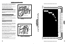
[AZIMUTH COLUMN READING WHEN EARTH STATION IS WEST OF SATELLITE]
[AZIMUTH COLUMN READING WHEN EARTH STATION IS EAST OF SATELLITE]
EARTH STATION ANTENNA LATITUDE (IN DEGREES NORTH OR SOUTH OF EQUATOR)
EARTH STATION ANTENNA AZIMUTH (IN DEGREES)
EARTH STATION ANTENNA AZIMUTH (IN DEGREES)
" L" IS THE DIFFERENCE BETWEEN THE EARTH STATION
ANTENNA SITE LONGITUDE AND THE SATELLITE LONGITUDE
AZIMUTH CHART
CHART 3
0°
5°
10°
15°
20°
25°
30°
35°
40°
45°
50°
55°
60°
65°
70°
75°
NORTHERN
HEMISPHERE
SOUTHERN
HEMISPHERE
WEST EASTWESTEAST
0
10
20
30
40
50
60
70
80
90
360
350
340
330
320
310
300
290
280
270
94