


6
ANTENNA ALIGNMENT PROCEDURE
Alignment with the satellite is obtained by setting polar-
ization, elevation and azimuth. Charts 1, 2 & 3 are to
determine the values for your earth station antenna site.
“∆L” is the difference between the earth station antenna
site longitude and the satellite longitude. Use “∆L” and
your earth station latitude to obtain polarization,
elevation or azimuth setting.
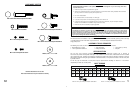
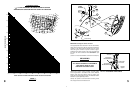
POLARIZATION OF FEED
Loosen feed horn M6 clamp bolts (12) and turn feed
clockwise or counterclockwise, depending on being east
or west of the satellite as shown on Chart 1. Align marks
on the horn clamp and appropriate mark on the horn
scale clamp is installed with arrow pointed toward antenna
as shown in Fig. 3.0. Keep cable groove on header in the
down position when adjusting polarization. NOTE:
Single Polarity Feed is factory assembled for vertical
polarity. If horizontal polarity is desired, rotate feed
90˚ (clockwise or counterclockwise).
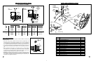
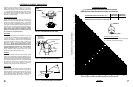
ELEVATION
To obtain elevation value for your satellite, refer to chart
2. Loosen bolts in curved slots of AZ/EL Housing ¹⁄₈ to
¹⁄₄ a turn (Ref. Fig. 3.1). Turn elevation adjustment bolt
clockwise to decrease elevation and counterclockwise
to increase elevation. Align the edge of clamp with
appropriate mark at the desired elevation reading
(Ref. Fig. 3.1). NOTE: Degree values shown on eleva-
tion scale are Beam; that is when the antenna face is
vertical mechanical elevation is 0˚, while the Beam
Elevation (signal) is 22.6˚. This will be an approximate
setting. Optimum setting achieved when fine tuning.
Temporarily tighten elevation bracket nuts.
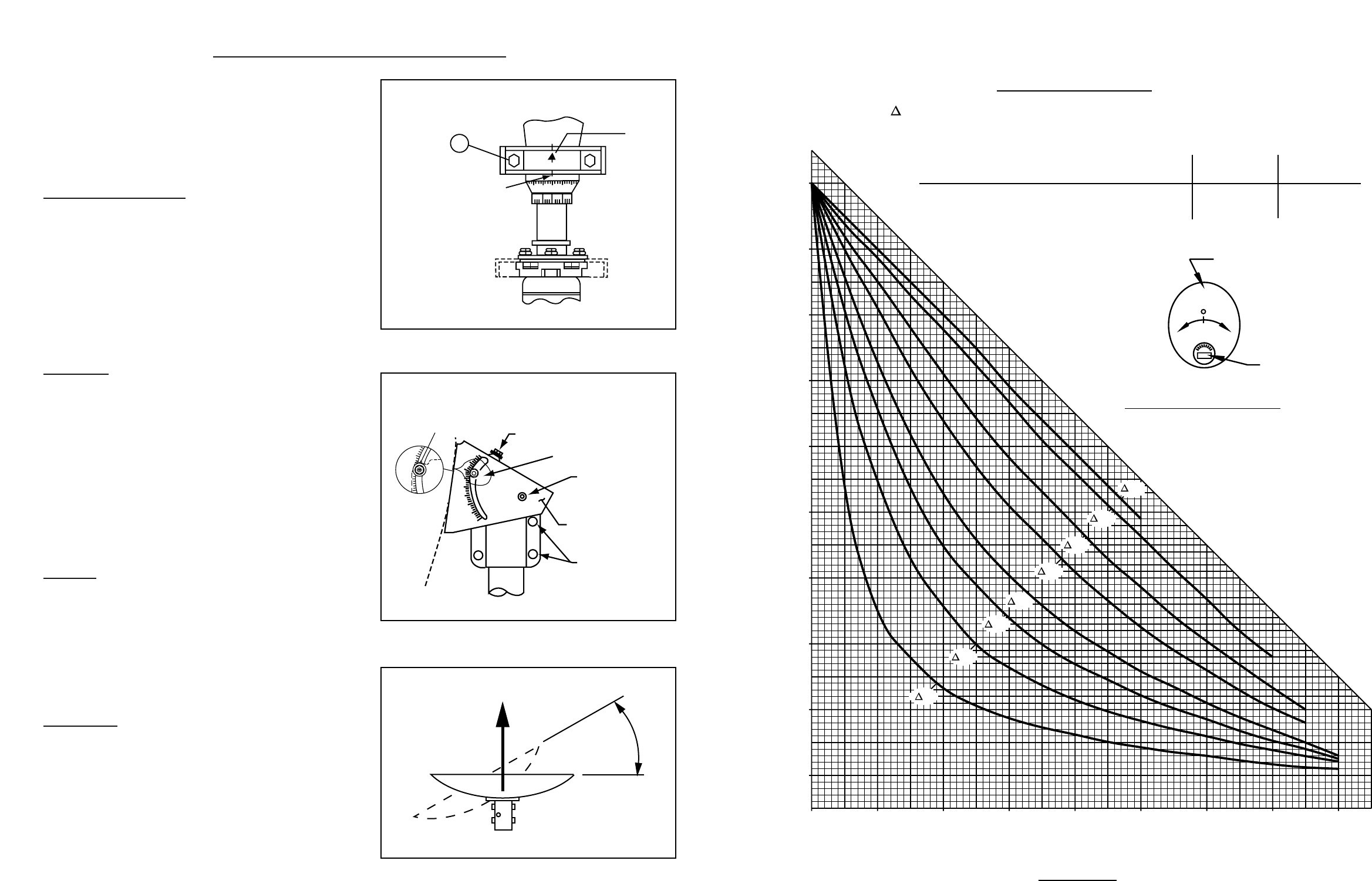
AZIMUTH
Use Chart 3 and determine your azimuth setting. Values
in chart must be adjusted for magnetic deviation for your
location for correct compass reading. Rotate the antenna
and mount, pointing it to the correct compass reading for
your location and satellite (Ref. Fig. 3.2). Slowly sweep
the antenna in azimuth until a signal is found. If the
desired signal is not found, increase or decrease
elevation setting and repeat the azimuth sweep.
FINE
TUNING
Use a signal strength measuring device for final adjust-
ments to obtain maximum antenna performance.
Alternate between elevation and azimuth fine tuning to
reach maximum signal strength until no improvement
can be detected. Tighten all hardware. Torque for M8
round head, square neck bolts is 15 N-m (11 ft-lbs).
-40
+40
0
12
ALIGNMENT
MARK
ARROW
FIG. 3.0
FEED
ASSEMBLY
FIG. 3.0 - POLARIZATION OF THE FEED
10˚
20˚
30
˚
40˚
50˚
60˚
70
˚
80˚
90˚
ELEVATION ADJUSTING BOLT
Align this edge
with desired
elevation setting
(shown at 22.5˚)
POINTER
PIVOT BOLT
AZ/EL
HOUSING
CLAMP
BOLT
20
˚
30˚
40˚
FIG. 3.1 - SETTING ANTENNA ELEVATION
AZIMUTH
FIG. 3.2 - ROTATING ANTENNA FOR AZIMUTH
0 1020304050607080
0
20
40
60
80
10
30
50
70
90
ANTENNA
FEED
NORTHERN SOUTHERN
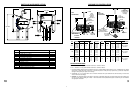
POLARIZATION CHART SIGN VALUES (+ OR -) HEMISPHERE HEMISPHERE
ANTENNA SITE WEST OF SATELLITE LONGITUDE - +
ANTENNA SITE EAST OF SATELLITE LONGITUDE + -
EARTH STATION LATITUDE IN DEGREES NORTH OR SOUTH OF EQUATOR
POLARIZATION + OR – (SEE ILLUSTRATION)
" L" IS THE DIFFERENCE BETWEEN THE EARTH STATION
ANTENNA SITE LONGITUDE AND THE SATELLITE LONGITUDE
POLARIZATION CHART
+ –
CHART 1
75°
60°
40°
30°
20°
15°
10°
5°
Feed Rotation (Facing Antenna)
For + Polarization, Rotate CCW (Counter Clockwise)
For - Polarization, Rotate CW (Clockwise)
7