


Operating Manual - WR-5e Remote Control for NE Products
2
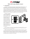
2. Wiring a WR-5e
The WR-5 uses a four conductor
phantom powered serial bus to con-
nect to its host unit or to subsequent
WR-5 units. Up to four WR-5 re-
motes can be powered from one host
unit. Ashly makes an Inline Power
Booster for use in applications that re-
quire more than four WR-5 remotes.
Four conductor telephone wire is
suitable for all wiring, as well as
CAT5, but if shielded wiring is used
be sure to ground the source end of
the shield. Under no circumstances
should shielding be left unconnected
to ground, as the added line capaci-
tance will degrade the data signal.
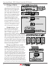
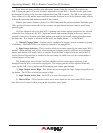
Wiring in Series: If more
than one WR-5 is being wired in
series, connect the next length of
four conductor bus wire from the rst
WR-5’s “LINK” connector to the
following WR-5 “INPUT” connector,
and so on, until the last WR-5 is wired. On the last
WR-5 in series wiring, and even if there is only one
WR-5, install the female jumper J6 on the back of
the pcb to terminate the serial data bus, and make
sure all prior WR-5 units have that jumper removed.
Maximum cable length for data integrity is 1,000 ft
between the host unit and the rst WR-5, and 1,000
ft between each subsequent WR-5.
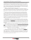
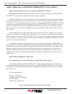
Wiring in parallel from a central
location: Some installations are more suited to
wiring multiple WR-5 units from one central loca-
tion rather than daisy-chaining one WR-5 to the
next. Using a punch down block wired to the host
unit’s data connector, each WR-5 uses one four
conductor cable terminated with a single euroblock
connector originating from the punch down block.
The +18 and Ground connections get parallel wired
to each WR-5 (up to four), but the data signal still
gets wired in series In the following manner: Wire
the host unit’s Data Out (pin 2) to the punch down
block, then out from there to the rst WR-5 Data In-
put (J2 pin 2), out J2 pin 1 back to an isolated punch