


3
Operating Manual - WR-5e Remote Control for NE Products
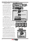
down block connection, then back out from there to the next WR-5 data input (J2 pin 2), out J2 pin
1 of that WR-5 back to yet another isolated punch down block connection, and so on, with the last
WR-5 Data Output (J2 pin 1) wired back to the host unit’s Data In connection. In this type of cen-
tralized wiring scheme, every WR-5 that returns its data signal back to the punch down block using
J2 pin 1 must have its J6 jumper installed. Without the J6 jumper installed, the data input signal on
J2 pin 2 is routed to J3 pin 2 for WR-5 series wiring as illustrated above. Maximum cable length for
data integrity is 1,000 combined feet between any two active units.
When more than four WR-5s are being used, an external DC power supply is re-
quired. The power supply must provide at least 13VDC and no more than 35VDC. In addition, each
WR-5 requires 30mA of current, (or 0.03 Amperes). To determine the minimum current rating of the
power supply in mA, multiply 30 times the number of WR-5 remotes to be used (Note: 1000mA =
1A).
Ashly offers an Inline Power Booster called the RPS-18 that provides 24VDC and 625mA
maximum current. It has common, euroblock-style terminals for easy insertion between the host
data port and WR-5 Input jack. Alternatively, it can be inserted between the J3-LINK jack of any
of the rst four WR-5 remotes, and the J2-INPUT jack of the next WR-5 in the chain. This latter
application can be useful to overcome voltage losses, caused by long cable runs to multiple remotes.
In either application, do not connect the +18V pin from the host unit’s Data connector to the exter-
nal supply +18V. It is possible to use the host unit’s +18V for the rst four WR-5 remotes and then
supplement any remaining WR-5 remotes with the inline power booster. Always connect the exter-
nal power supply ground to the host unit’s Data connector ground.
Cable Length - Two things to consider when running cable to the WR-5 are data integrity
& power supply voltage. Active buffers (line drivers) in the WR-5 maintain data integrity, allowing
up to 1,000ft (304m) of cable between devices. Thus, a maximum cable length up to 1,000ft may be
used between the Remote Data Port and WR-5 remote, and another cable up to 1,000ft may be used
from the WR-5 Link jack to an additional WR-5 remote, and so on. Hence each WR-5 functions as a
data repeater.
However, long cable runs act as resistors, which reduce the DC power supply voltage delivered
to the WR-5. Each WR-5 requires a minimum of 13VDC measured across J2-INPUT jack terminals
3 & 4. It is vital to keep track of the power supply voltage drop across each successive cable run to
those pins. For example, typical CAT5 (24AWG) wire has a DC resistance of 0.026 ohms per foot.
Since there are two conductors, (V+ and GND), the resistance is doubled to 0.052 ohms per foot.
Therefore, voltage drop across CAT5 wire can be computed as:
Voltage drop = current (in Amps) * 0.052 (ohms) * cable length in feet
Where current is computed at 30mA (0.03A) per WR-5. If the supply voltage at the WR-5 falls
below 13VDC, the WR-5 will not power up. TIP: To minimize voltage loss over cable length, use
multiple conductors for V+ and GND, (WR-5 terminals 3 & 4). For example, CAT5 wire has a total
of eight 24AWG conductors. Use one pair for wiring up the two data terminals. Use three conduc-
tors in parallel for V+, and use the three remaining conductors for GND. This effectively reduces
the power supply voltage drop by a factor of three.