AVerMedia User’s Manual
EYES Pro/MP2016/MP3000/MP5000
9
Cameras need to be installed according to the numerical order displayed
on the diagrams above. Whether you have one, two, three or four
video cards, the pattern is the same - cameras will be installed from
left to right starting with the top row for EYES Pro and from top
to bottom beginning with the left-most column for
MP2016/MP3000/MP5000.
1.8 Connecting External Sensor/Relay
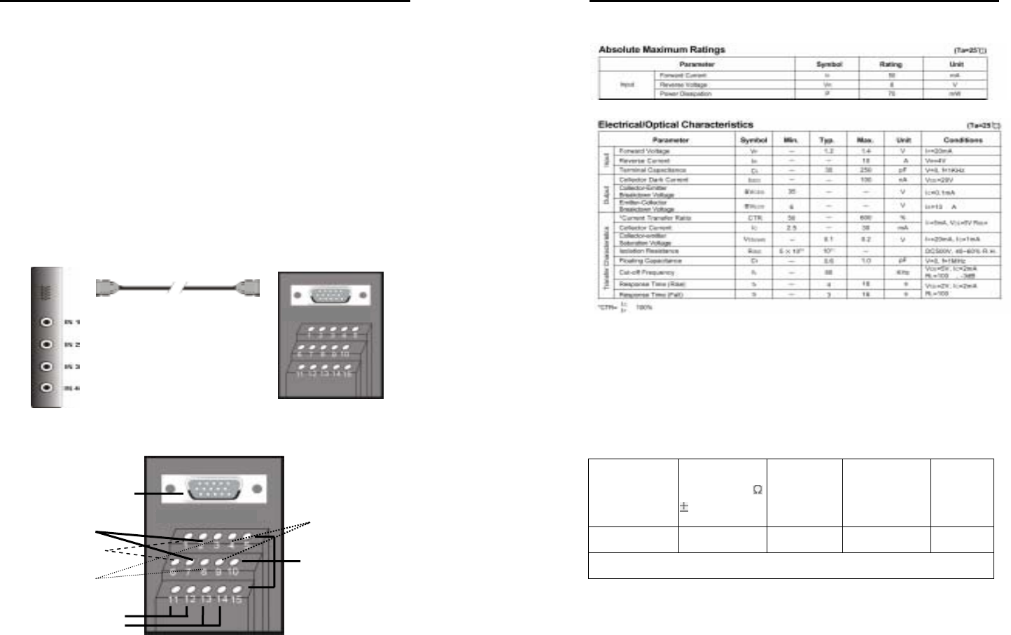
Each system can come with optional External I/O Boxes and D-type 15-
pin connector cables enabling you to connect sensor inputs and relay
outputs. The pin signals and specifications for the external I/O Box and
the D-type 15-pin connectors are described below.
D-type 15-pin Connector Cable
External I/O Box
Video Card
External I/O Box
Relay Outputs 3
Sensor Input 3
Rela
y
Out
p
ut 2
Sensor Input 2
Sensor Input 1
Relay Output 1
D-type 15-pin connector
Sensor Input 4
AVerMedia User’s Manual
EYES Pro/MP2016/MP3000/MP5000
10
Sensor Input Specification
Relay Output Specification
Surge strength: 1500 VAC
Nominal power 200mw ~ 360mw
Operating power 110mw ~ 200mw
COIL RATINGS (at 20
o
C)
Coil Nominal
Voltage
(VDC)
Coil
Resistance (
10% )
Pick-up
Voltage
(VDC)
Drop-Out
Voltage
(VDC)
Nominal
Current
(mA)
5 125 3.75 0.5 40
* Max Continuous Voltage at 20
o
C : 110% of Coil Nominal Voltage


