


FOSTCDR2999 Manual 1
B&B Electronics Mfg Co Inc – 707 Dayton Rd - PO Box 1040 - Ottawa IL 61350 - Ph 815-433-5100 - Fax 815-433-5104
Description
The FOSTCDR is designed to provide the most versatile
connection possible between any asynchronous serial equipment
using Fiber Optic cable. It allows any two pieces of asynchronous
serial equipment to communicate full or half-duplex over two fibers at
typical distances up to 2.5 miles. The converter can also be set up in
"Repeater" mode to create a multi-drop master/slave configuration,
allowing one serial device to talk to multiple slave devices around a
fiber ring. The DIN rail mountable box makes it ideal for industrial
cabinets and enclosures.
RS-232 data signals up to 115.2K bps and RS-422, or RS-485
data signals up to 460K bps are supported. Different standards can
be mixed and matched to allow RS-232 devices to connect to your
RS-422 or RS-485 system. This means the FOSTCDR can replace
converters and isolators when connecting remote devices, while
providing the EMI/RFI and transient immunity of optical fiber.
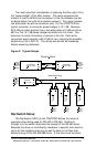
The FOSTCDR supports both the Transmit and Receive data
lines, and provides full hardware control of the RS-422/485 driver with
B&B's Automatic Send Data Control circuit. Timeouts are dip-switch
selectable between 0.10 and 2.2 ms. All serial connections are
provided on terminal blocks, while the multi-mode fiber is connected
via two ST connectors. The unit is powered by 10 to 30VDC at 140
mA max.
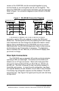
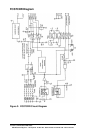
RS-232 Connections
Connection of the FOSTCDR is simple and straightforward. The
RS-232 driver and receiver are connected to 2 terminal blocks. The
RS-232 DATA OUT is on terminal block (A), and the RS-232 DATA IN
is on terminal block (D). Ground is located on terminal block (B) and
(C), and power comes in on terminal block (F).
RS-422 & RS-485 Connections
The RS-422/485 driver and receiver are connected to 4 terminal
blocks. Signal ground is on terminal block (M), and power comes in
on terminal block (J). When connecting to a four-wire RS-422/485
device or system, connect the output of your device to terminal block
(L) (RDB or RD+) and terminal block (K) (RDA or RD+). Connect the
input to your device to terminal block (H) (TDB or TD+) and terminal
block (G) (TDA or TD-). For two-wire RS-485 systems, the driver and