


FOSTCDR2999 Manual 5
B&B Electronics Mfg Co Inc – 707 Dayton Rd - PO Box 1040 - Ottawa IL 61350 - Ph 815-433-5100 - Fax 815-433-5104
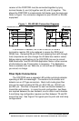
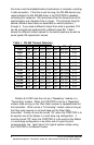
Table 2: 422/485 Switch Settings
Position 7
TX Enable
Position 8
RX Enable
RS-485 2-Wire Mode
(half duplex)
ON ON
RS-485 4-Wire Mode
(full duplex)
ON OFF
RS-422 Mode
(full duplex)
OFF OFF
Positions 7 and 8 of SW1 determine when the RS-422/485 driver
and receiver are enabled. Position 7 controls the driver and Position 8
controls the receiver. For RS-422 operation, set both switches to the
“Off” position. For multi-drop RS-485 four-wire systems, position 7
should be “On” and position 8 should be “Off.” This allows the
receiver to be enabled all of the time and eliminates some possible
timing problems. For RS-485 two-wire systems, both switches
should be in the “On” position. This disables the RS-422/485 receiver
whenever the driver is enabled, preventing data from being echoed
back to the fiber side of the FOSTCDR. Table 2 illustrates the switch
settings for typical setups.
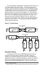
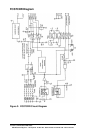
Multi-Drop Operation
A multi-drop configuration can be created by forming a ring of
FOSTCDRs. Each transmitter is tied to the following converter’s
receiver, starting at a master node and continuing around to each
slave and back to the master. By setting SW1:6 to the “On” position
on the slaves, all data sent from the master or preceding slaves is
echoed back out the fiber transmitter to the rest of the slaves and
eventually back to the master node.
Because all data is echoed back, there are special
considerations when constructing a multi-drop system. The master
will see its own transmitted data. This means that the master device
must be full-duplex (RS-232, RS-422, or four-wire RS-485) and that it
must be capable of ignoring or otherwise accepting its own echoed
transmission. Slaves must also be able to accept data from previous
slaves in the loop.