


FOSTCDR2999 Manual 3
B&B Electronics Mfg Co Inc – 707 Dayton Rd - PO Box 1040 - Ottawa IL 61350 - Ph 815-433-5100 - Fax 815-433-5104
The most important consideration in planning the fiber optic link is
the “power budget” of the fiber modem. This value represents the
amount of loss in dB that can be present in the link between the two
modems before the units fail to perform properly. This value includes
line attenuation as well as connector loss. For the FOSTCDR the
typical connector to connector power budget is 12.1 dB. Because
62.5/125 µm cable typically has a line attenuation of 3 dB per Km at
820 nm, the 12.1 dB power budget translates into 2.5 miles. This
assumes no extra connectors or splices in the link. Each extra
connection would typically add 0.5 dB of loss, reducing the possible
distance by 166 m (547 ft.). The actual loss should be measured
before assuming distances.
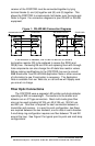
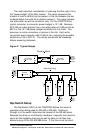
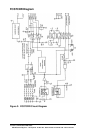
Figure 2: Typical Setups
Dip-Switch Setup
The Dip-Switch (SW1) on the FOSTCDR defines the mode of
operation when being used for RS-422 or RS-485. Positions 1
through 5 on the switch determine the timeout of the RS-485 driver.
Because the driver is controlled by hardware, a specific time must be
set to tell the hardware how long to wait for data on the fiber side
before turning off the RS-422/485 driver. If this time is set too short,
TX
RX
FOSTCDR
RX
TX
FOSTCDR
RS-232
RS-422
or RS-485
Device
Duplex
Multimode
Fiber
or System
RS-232
RS-422
or RS-485
Device
or System
SW1:6 = OFF SW1:6 = OFF
Point to Point
TX
RX
FOSTCDR
RX
TX
FOSTCDR
RS-232
RS-422
or RS-485
Device
Multimode
Fiber
or System
RS-232
RS-422
or RS-485
Device
or System
RX
TX
FOSTCDR
RS-232
RS-422
or RS-485
Device
or System
RX
TX
FOSTCDR
RS-232
RS-422
or RS-485
Device
or System
Full Duplex
SW1:6 = OFF
SW1:6 = ON
SW1:6 = ON
SW1:6 = ON
MASTER
SLAVE
SLAVE
SLAVE
Multi-Drop Ring