


2 FOSTCDR2999 Manual
B&B Electronics Mfg Co Inc – 707 Dayton Rd - PO Box 1040 - Ottawa IL 61350 - Ph 815-433-5100 - Fax 815-433-5104
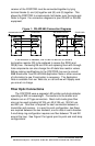
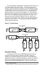
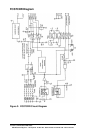
receiver of the FOSTCDR must be connected together by tying
terminal blocks (L) and (H) together and (G) and (K) together. This
allows the FOSTCDR to communicate half-duplex over the same pair.
Refer to Figure 1 for connection diagrams to your RS-422 or RS-485
equipment.
If termination is needed, the PCBD is laid out to allow a
termination resistor (Rt) to be soldered in across the RD(A) and
RD(B) lines. Removing R8 and R16 and replacing them with through-
hole components can also change the off-state bias resistor values.
Before making modifications to the FOSTCDR, be sure to consult
B&B Electronics’ free RS-422/485 Application Note or other sources
of information to see if termination is necessary. The Application
Note is available from our Web site, or call and we will happily send
you one at no charge.
Fiber Optic Connections
The FOSTCDR uses a separate LED emitter and photo-detector
operating at 820 nm wavelength. Connections to the emitter and
detector are on ST type connectors. Most multi-mode glass fiber
size can be used including 50/125 µm, 62.5/125 µm, 100/140 µm,
and 200 µm. One fiber is required for each connection between a
transmitter and receiver. In a point to point configuration, two fibers
are required between the two modems, one for data in each direction.
A multi-drop ring configuration requires one fiber between TX and RX
around the loop. See Figure 2 for typical point to point and multi-drop
configurations.
Figure 1: RS-422/485 Connection Diagrams
422/485 4W Device
TD A (-)
TD B (+) (L) RD B
(K) RD A
(H) TD B
(G) TD ARD A (-)
RD B (+)
(M)GND
FOSTCDR
485 2 Wire Device
Data A (-)
(L) RD B
(K) RD A
(H) TD B
(G) TD A
Data B (+)
(M)GND
FOSTCDR