


724-746-5500 | blackbox.com
724-746-5500 | blackbox.com
Page 31
ACX1MT
Chapter 2: Overview
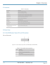
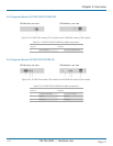
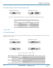
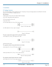
2.6.16 USB 2.0 Module ACX1MT-U2-SM/ACX1MR-U2-SM
CPU Module, rear view CON Module, rear view
Figure 2-17. ACX1MT-U2-SM module (CPU module) and ACX1MR-U2-SM module (CON module).
Table 2-22. ACX1MT-U2-SM/ACX1MR-U2-SM module components.
CPU unit CON unit
1 Service port 1 Service port
2 Connect to interconnect cable 2 Connect to interconnect cable
3 To CPU: USB 2.0 3 Connect to USB 2.0 devices
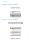
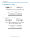
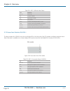
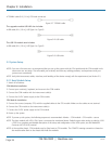
2.7 Status LEDs
2.7.1 Status Basic Module
The basic module has a multicolor LED on both sides to indicate overall status. It also has two additional LEDs on the back side to
indicate the connection status.
CPU module, rear view CON module, rear view
Figure 2-18. Status LEDs on the basic module.
Table 2-23. LED 1 and 2: Connection Status.
Position LED Status Description
1 Failure LED (green)
Off Connection available
On or Flashing Connection failure (flashing for about 20 seconds following a connection failure)
2 Status LED (green)
Flashing No connection via interconnect cable
On Connection available