


724-746-5500 | blackbox.com
Page 36
ACX1MT
724-746-5500 | blackbox.com
Chapter 3: Installation
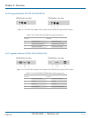
• TOSLINK cable (6-ft. [1.8 m], F05 male connector)
Figure 3-7. TOSLINK cable.
The upgrade module USB-HID also includes:
• USB cable (6-ft. [1.8 m], USB Type A to Type B)
Figure 3-8. USB cable.
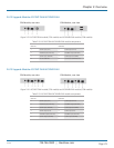
The USB 2.0 module also includes:
• USB cable (6-ft. [1.8 m], USB Type A to Type B)
Figure 3-9. USB cable.
3.2 System Setup
NOTE: I f you are a first-time user, we recommend that you set up the system with the CPU module and the CON module in the
same room as a test setup. This will enable you to identify and solve any cabling problems, and experiment with your
system more conveniently.
NOTE: Verify that interconnect cables, interfaces, and handling of the devices comply with the requirements (see Section 3.1).
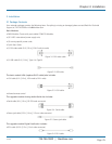
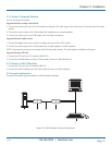
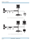
3.2.1 Basic Module Setup
1. Switch off all devices.
CON Module Installation
2. Connect your monitor(s), keyboard, and mouse to the CON module.
3. Connect the CON module with the interconnect cable(s).
4. Connect the 5-VDC power supply to the CON module.
CPU Module Installation
5. Connect the source (computer, CPU) with the supplied cables to the CPU module. Make sure the cables are not strained.
6. Connect the CPU module to the interconnect cable(s).
7. Connect the 5-VDC power supply to the CPU module.
8. Power up the system.
NOTE: To power up the system, the following sequence is recommended: Monitor – CON module – CPU module – source.
NOTE: The basic module with VGA / DVI-I input is connected as mentioned above. Default output video setting is scaled to 1024
x 768. For a complete and detailed description of the setup and configuration of the VGA option, see the Media/DVI
Converter (ACS411A-R2) manual.
NOTE: In the modular chassis, CON modules may be fitted next to CPU modules. The CON/CPU naming convention is based on
the module rather than on the chassis that holds the modules.