Divar 700 Series Operating instructions | en 59
Bosch Security Systems Installation and Operation manual F.01U.246.471 | v3.6 | 2011.11
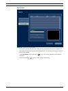
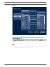
– Earliest recording - displays date and time of the earliest (oldest) recording on disk.
– Latest recording - displays date and time of the latest (newest) recording on disk.
– Total Disk Size - displays the total installed disk space.
– RAID status - displays enabled if the disks are used as a RAID array.
– Time till overwrite appr. - estimated time video is retained until overwriting.
– Authenticity check... - click to check authenticity of recorded audio and video.
– Disks in active disk set:
– The list shows which internal disks or LUNs on iSCSI arrays are available for
recording in the active disk set.
– The disk or LUN on which recording is currently performed or scheduled is shown
with a red dot. Other disks or LUNs in the disk set which are available for recording
are marked with a green dot.
When RAID is activated all 4 local drives show a red dot. iSCSI LUNs are not avail-
able for recording when RAID is activated.
– The active disk set is selected during boot if the unit detects multiple disk sets. The
active disk set can also be changed in the Storage configuration pages.
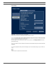
Video signals
The video signals tab displays the system video mode (PAL or NTSC) and video input status.
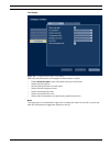
Recording status
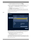
Currently active profile - displays current profile
Alarm recording at input - displays which inputs are in alarm recording mode
Motion recording at input - displays which inputs are in motion recording mode
Current recording status - displays video and audio recording mode and status for each input
Sensors
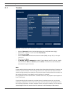
Displays actual temperature and voltage sensor values. If temperature levels are outside of
the normal range, the displayed values are yellow. If this occurs, check that the ambient
temperature is within the recommended specifications and that there is proper air ventilation.
If the temperature reaches a critical level, the unit automatically shuts down. To restart the
unit, disconnect the power cord, wait for at least 30 seconds, and then reconnect the power
cord.
Table 5.1 Temperature sensors
Sensor name Lower limit Upper limit
Processor 5 °C / 41 °F 100 °C / 212 °F
Air inlet 5 °C / 41 °F 45 °C / 113 °F
Air outlet 5 °C / 41 °F 55 °C / 131 °F
Hard disk #1 5 °C / 41 °F 55 °C / 131 °F
Hard disk #2 5 °C / 41 °F 55 °C / 131 °F
Hard disk #3 5 °C / 41 °F 55 °C / 131 °F
Hard disk #4 5 °C / 41 °F 55 °C / 131 °F


