


27
ADDITIONAL INFORMATION
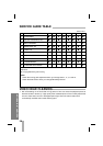
SELF-DIAGNOSIS
This function informs you of error messages to help solve problems more easily.
When the VCR malfunctions, an error code is displayed in the VCR indicator panel.
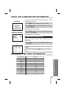
DISPLAY DESCRIPTION INPUT SIGNAL CIRCUIT STATUS SERVICE POINTS
Loading Motor Error
Tape Loading Error
Tape Eject Error
Reel Rotational Error
Drum Motor Error
• Mode Switch
S1,S2,S3,S4
• Load Motor +, -
• Mode Switch
S1,S2,S3,S4
• Load Motor +, -
• Mode Switch
S1,S2,S3,S4
• CST IN Switch
• Load Motor +, -
• Supply/Take-up
Reel Pulses
• CFG
• DFG Switch
• DPF
• Mode Switch Position not
changed within 6 seconds
after cassette loading attempt.
• Mode Switch Position not
changed within 6 seconds
after cassette loading attempt.
• CST Switch must be activat-
ed within 3 seconds, other-
wise unit shut down will occur.
• CFG Signal present, but take-
up pulses are missing.
(Capstan motor running.)
• Drum Motor (Slow Start)
• Motor must be up to speed
within 3 seconds of operation.
• Loading Motor Drive
IC
• Loading Motor
• Mode Switch
• Mode Switch
contacts
• CSTIN Switch
contacts
• Capstan belt
• Idler and reel gears
damaged
•Drum Motor and
Control Circuits
ERROR CODE TABLE
•
When a malfunction occurs in the VCR, press the POWER button on the front of VCR to oper-
ate normally.
• An error message (Err) appears in the display continuously when any button is pressed;
contact your dealer or service center.