


Installation Instructions
6
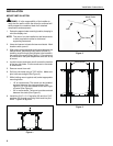
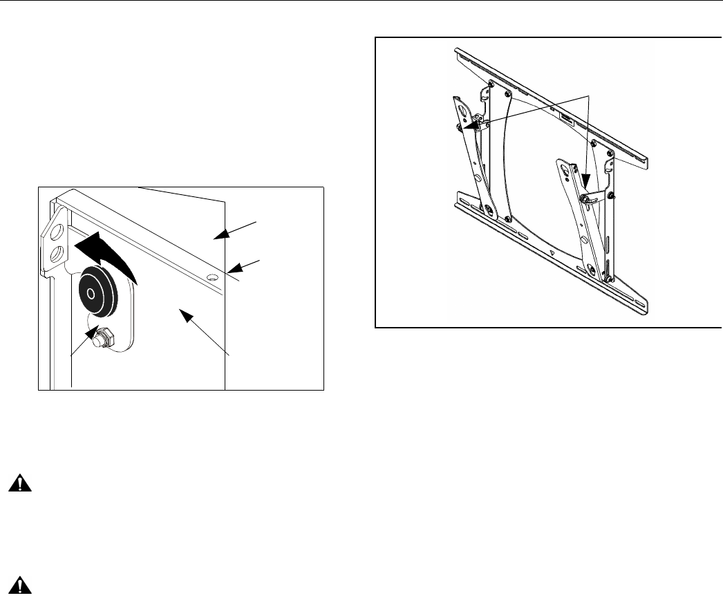
3. Secure display by rotating both Q-Latches to the fully
LATCHED position (See Figure 8). If one or both Q-
Latches do not fully engage, ensure the mounting
buttons are fully seated in the teardrop slots.
NOTE: A hole is provided in the Q-Latch and faceplate
to accommodate the insertion of a padlock or
similar locking device.
Figure 8
TILT ADJUSTMENT
CAUTION: Loosen the nut only. To avoid equipment
damage, do not remove the nut from the mount.
1. Using 1/2" socket wrench, loosen the tilt adjustment
nut on both arms of the mount (See Figure 9).
CAUTION: Do not over-tighten the nuts. Over-
tightening the nuts may cause excessive wear and may
damage your mount.
2. Tilt display to the desired position. Tighten both nuts.
REMOVE THE DISPLAY
1. Disconnect all power/audio/video cables.
2. UNLATCH both Q-Latches to unlock the display (See
Figure 8).
3. With the aid of another person, lift the display up and
out of the teardrop slots in the mount.
Figure 9
Q-Latch
Mounting
Button
Faceplate
Display
LATCHED
Tilt Adjustment Nuts