


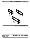

RMF2/RLF2/RXF2 Installation Instructions
8
Install Wall Plate to Wall - Concrete or
Concrete Block
WARNING: Failure to provide adequate structural strength
for this component can result in serious personal injury or
damage to equipment! It is the installer’s responsibility to
make sure the structure to which this component is attached
can support five times the combined weight of all equipment.
Reinforce the structure as required before installing the
component. The wall to which the mount is being attached
may have a maximum drywall thickness of 5/8" (1.6cm).
WARNING: ELECTRICAL SHOCK HAZARD! CUTTING
OR DRILLING INTO ELECTRICAL CORDS OR CABLES
CAN CAUSE DEATH OR SERIOUS PERSONAL INJURY!
ALWAYS make certain area behind mounting surface is free
of electrical wires and cables before drilling or installing
fasteners.
WARNING: EXPLOSION AND FIRE HAZARD! CUTTING
OR DRILLING INTO GAS PLUMBING CAN CAUSE DEATH
OR SERIOUS PERSONAL INJURY! ALWAYS make certain
area behind mounting surface is free of gas, water, waste, or
any other plumbing before cutting, drilling, or installing
fasteners.
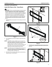
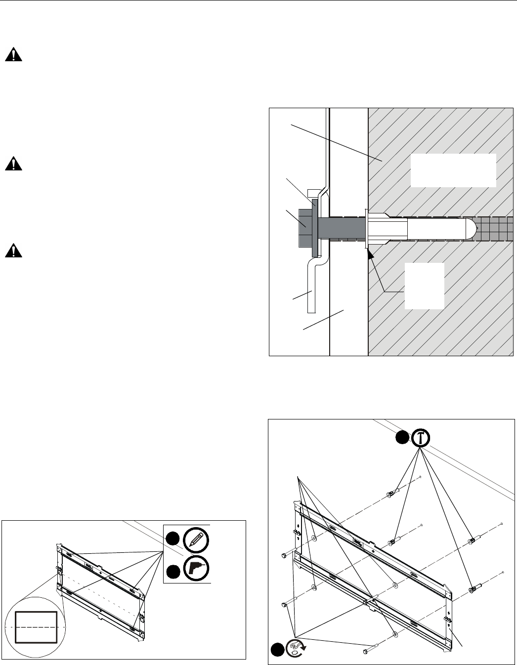
1. Unfold wall plate (A) to prepare it for mounting to wall. (See
Figure 1)
2. Level wall plate (A) and mark locations of pilot holes at
desired mounting location. (See Figure 5)
IMPORTANT ! : The RMF2-RLF2-RXF2 mounts are
designed to be mounted to 8" concrete or 8"x8"x16"
concrete block.
NOTE: For the RLF2, either the inner or outer four holes may
be used.
NOTE: For the RXF2, use the outer four holes and the two
middle holes on wall plate for installation.
NOTE: The vertical center of the display will be even with the
center line indicated on the labels located directly
below each hinge. Keep this in mind when determining
mounting location. (See Figure 5)
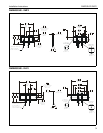
Figure 5
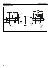
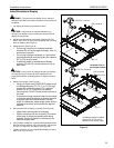
3. Drill 5/16" (8mm) diameter pilot holes into wall at marked
locations. Holes must be drilled at least 3 1/4 inches deep.
(See Figure 5)
4. Install four or six concrete anchors (E) into drilled holes. Use
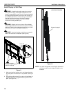
a hammer to tap anchors into holes. (See Figures 6 and 7)
IMPORTANT ! : The anchors must be installed through
any wall covering until flush with the concrete wall. (See
Figure 6)
Figure 6
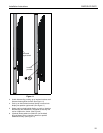
5. Using 1/2" (12.7mm) wrench, install screws (C) through flat
washers (D), wall plate (A) and into concrete anchors (E).
(See Figure 7)
Figure 7
CENTER
LINE
2
3
x 4 or 6
Anchor
flush with
concrete
wall
Anchor (E)
wall covering
(A)
Pilot Hole -
5/16 x 3 1/4"
(M8 x 82.5mm)
(C)
(D)
concrete
wall
(A)
(D) x 4 or 6
(E) x 4 or 6
5
(C) x 4 or 6
4