


Installation Instructions RMF2/RLF2/RXF2
9
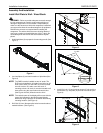
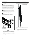
Install Brackets to Display
WARNING: The minimum hole pattern size is 100mm x
100mm for the RMF2 and 200mm x 200mm for the RLF2 and
the RXF2.
1. Lay display face down on protective surface.
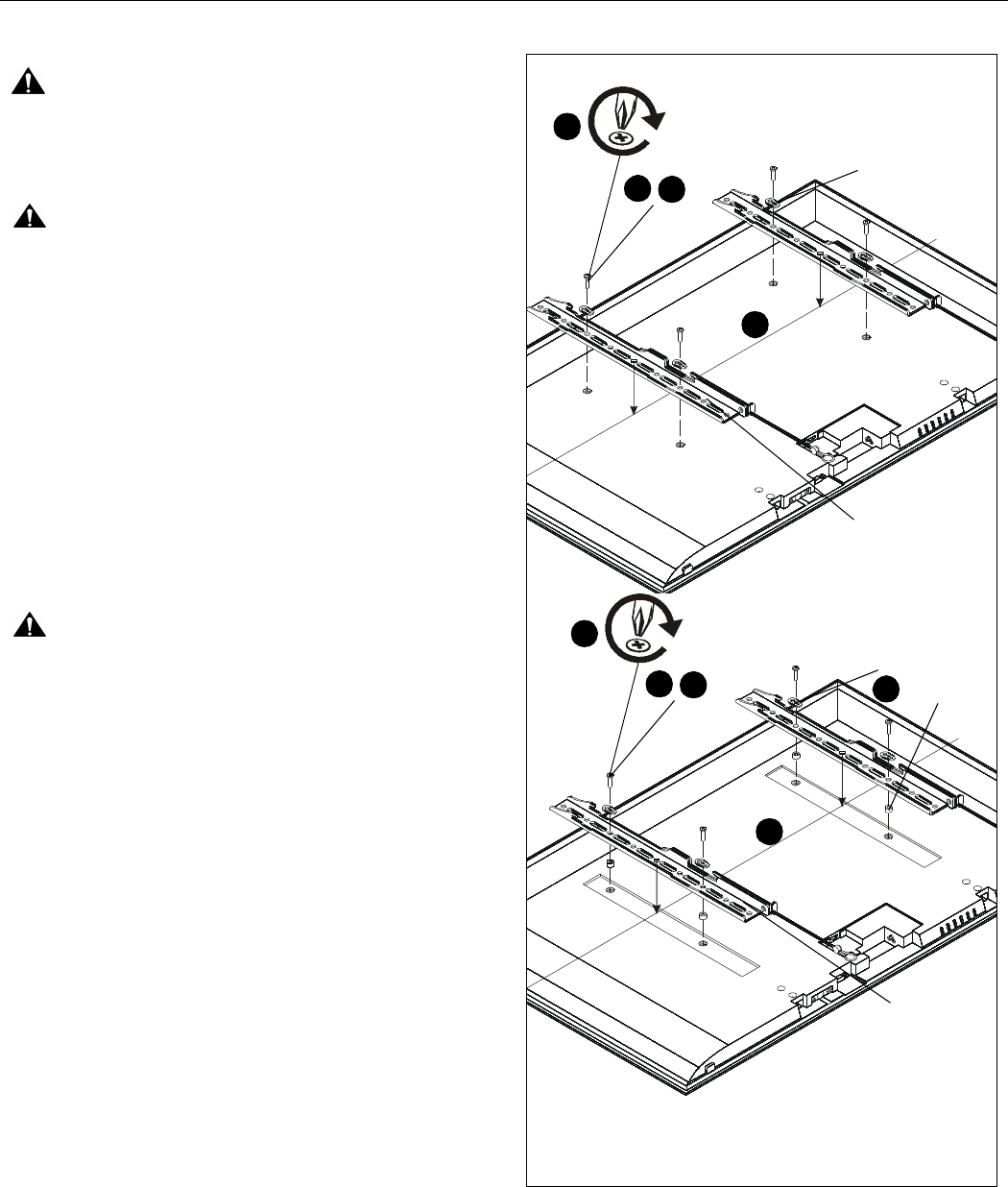
CAUTION: Using screws of improper diameter may
damage your display! Proper screws will easily thread into
display mounting holes.
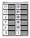
2. Select screw diameter by examining hardware (FA-FO)
(8mm, 6mm, 5mm, or 4mm) and comparing with mounting
holes on display. (See Figure 8)
3. Select spacers: (See Figure 8)
• If mounting holes are not recessed and both
brackets (B) can lay flat against display, then no
spacers are required.
• If mounting holes are recessed, or if protrusions
prevent brackets (B) from laying flat, then spacers
(FP or FQ) must be used.
• If additional depth is needed behind display,
spacers (FP and FQ) can be stacked on top of
each other.
CAUTION: Using screws of improper length may damage
your display! Proper screws will have adequate thread
engagement without contacting bottom of display mounting
holes.
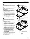
4. Select screw length: (See Figure 8)
• Using your hand, insert SHORTEST length screw
of selected diameter (FA, FE, FI or FL) through
bracket (B), universal washer (FS), selected
spacer (FP or FQ, if required), into display
mounting hole. Do NOT thread screw into hole at
this time.
• Proper screw length requires base of screw head
to protrude above flat washer a distance equal to
or greater than the screw diameter. If screw
length is inadequate, select longer screw. Select
shortest screw which will protrude the required
distance.
5. Place brackets (B) on display, ensuring: (See Figure 8)
• Upper hooks are towards top of display.
• Center of brackets (B) are as close to the center
of the back of display as possible after being
installed. Center of bracket is indicated by the
diamond-shaped hole.
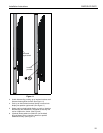
6. Using Phillips screwdriver, carefully install selected screws
through universal washers (FS), brackets (B), and spacers
(FP or FQ, if required), into display. (See Figure 8)
7. Tighten all screws. Ensure all applicable display mounting
holes (4, 6, or 8) are used.
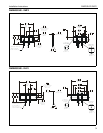
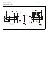
Figure 8
(non-recessed holes)
(recessed holes or
6
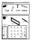
(FA-FO) x4,x6,x8
(FS) x4,x6,x8
2
4
5
6
(FA-FO) x4,x6,x8
2
4
5
(FS) x4,x6,x8
(FP or FQ)*
3
(B) x 2
(B) x 2
*If additional depth is needed,
spacers (FP or FQ) can be
stacked on top of each other
extra depth needed)