


Compur Statox 4120
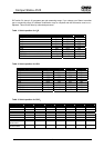
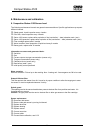
Table 8: Switch position for SO
2
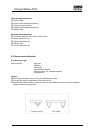
Table 9: Switch position for NO
2
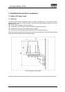
Measuring range: 0-0,5 ppm Measuring range: 0-15 ppm
S1/1 OFF S1/1 ON
S1/2 ON S1/2 ON
S1/3 ON S1/3 ON
S1/4 OFF S1/4 ON
S1/5 ON S1/5 ON
S1/6 ON S1/6 ON
S1/7 ON S1/7 ON
S1/8 ON S1/8 ON
E-PROM Index sensor head 21 E-PROM Index sensor head 21
E-PROM Index control module 04 E-PROM Index control module 04
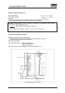
4. Compur Statox 4120 operation
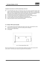
4.1 Start - up
Connecting the Statox 4120 rack to mains (230 V/ 50 Hz or 115 V 60 Hz) activates the system.
The green LED will be flashing until the initial data exchange with the sensor head has been
finalised. It flashes also if the calibration box is connected.
The green LED stays on as soon as the system is in the detection mode.
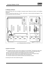
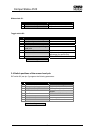
4.2 Alarm thresholds
A1: Push and hold button A1 for 5 s to obtain a display of the alarm threshold on the bar graph.
A2: Push and hold button A2 for 5 s to obtain a display of the alarm threshold on the bar graph.
4.3 Detection mode
The green SR LED is on and the actual measured value is displayed on the bar graph.
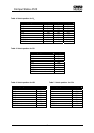
4.4 Self test of the system
Every 24 hours the entire system tests itself. During the test all LED`s are on and the bar graph
dispays full scale. The analog output goes to full scale. (How to avoid this see chapter 7 and 8).
If an error is detected, the red LED SF goes on.
At temperatures below –20°C (-4°F) the self test can not be activated.
18