


Compur Statox 4120
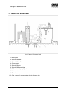
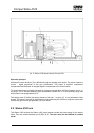
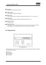
2.3 Statox 4120 control module
Each Statox 4120 Control module has its own power supply. The intrinsically safe sensor head supply
circuit is supplied by a separate secondary winding.
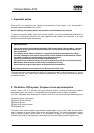
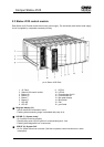
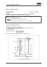
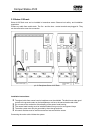
pic.4: Statox 4120 Rack
1 19“ Rack 9 LED A1
2 Statox 4120 control module 10 LED A2
3 Button A2 11 Potentiometer for A2
4 Button A1 12 Potentiometer A1
5 Button T 13 Bar graph display
6 Button R 14 Blind panel
7 LED SR 15 Rail
8 LED SF 16 ppm Scale
Bargraph display (13)
- Actual measured concentration value.
- Flashing when measuring range is exceeded and pump is on.
LED SR (7) „System ready“
- On if system is working properly.
- Flashing after power up until system is communicating fault - free.
- Flashing while diagnostic box is connected.
LED SF (8) „System Fail“
- On if a system failure has occurred. (Self test not passed, communication error, cable
8
interrupted).