


16
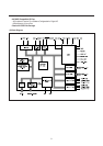
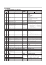
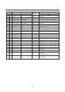
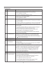
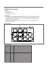
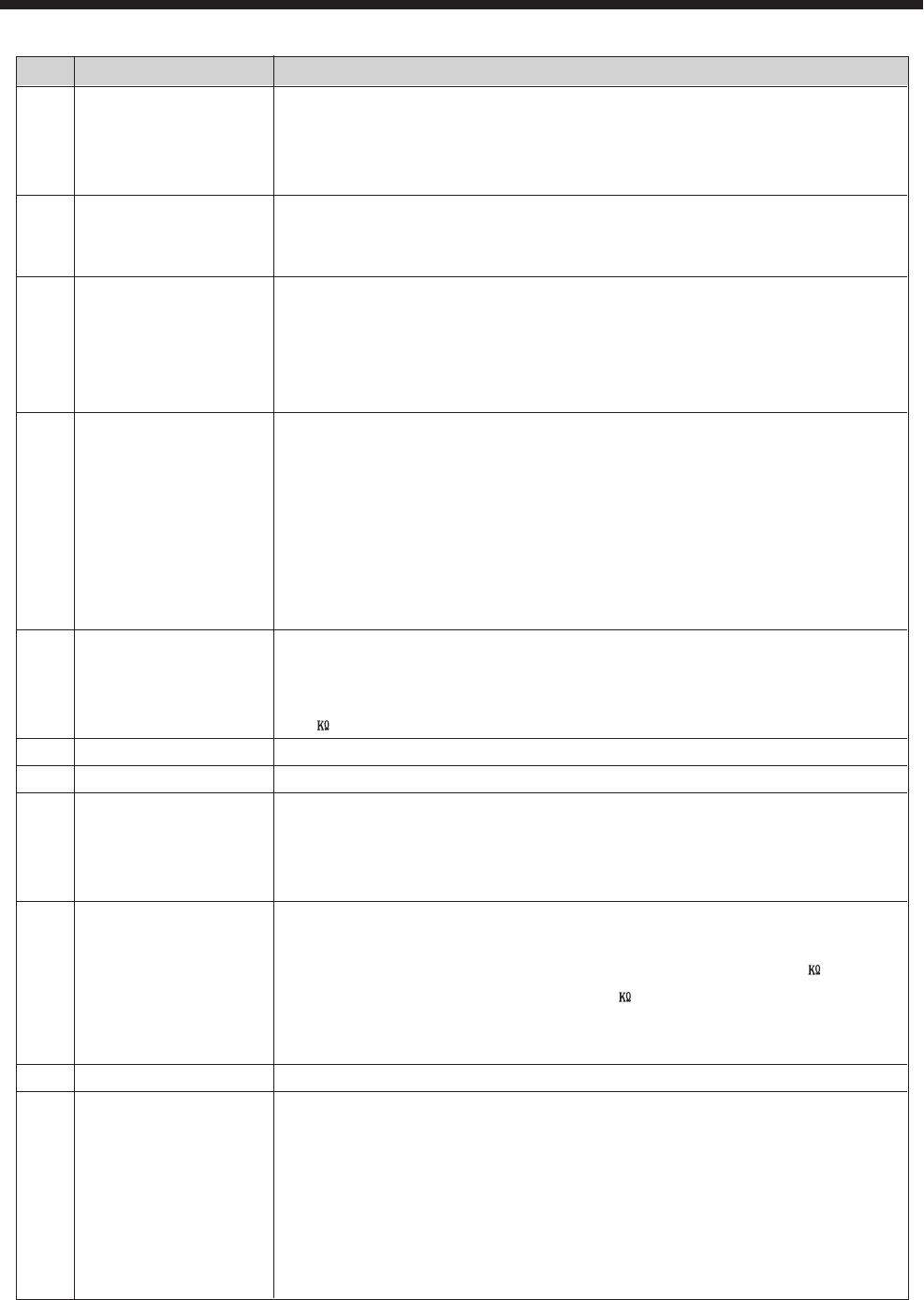
(4) Pin Description
No Name Description
1 SOUND IF INPUT The sound equivalent input impedance is 8k5 ohm // 5pF which has to be
taken into account for proper termination of the ceramic filters.
The DC impedance is very high.
The minimum input signal for catching is l mV rms.
2 EXT AUDIO INPUT An external sound signal (500mVrms) for example from SCART can be
applied to this pin via a coupling capacitor.
The input impedance is 25kohm.
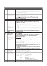
3 VCO REF FILTER The IF VCO tuned circuit is applied to these pin.
4 Its resonance frequency must be two times the IF-frequency and in between a
range of 64-120MHz.
This range is suitable for the IF standards as 33.4, 38.9, 45.75 and 58.75MHz.
The VCO frequency can be adjusted by I2C bus so a fixed coil can be used.
5 PLL LOOP FILTER The PLL loopfilter is a first order filter with R=390 ohm and C = 100nF in
series to ground.
The loopfilter bandwidth is 60kHz and is optimal for both fast catching and
sufficient video suppression for optimal sound performance.
Sound performance can theoretically be improved by adding a small
capacitor (approx.0- 4.7nF) between pin 5 and ground.
This however must be evaluated further because the normal video signal
response should not be effected.
6 IF VIDEO OUTPUT Although the video output impedance is low it is recommended to avoid
high frequency current in the output due to for instance sound trap filters.
This can be achieved by means of an emitter follower at the video output with
a 1 resistor in series with the base.
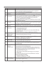
7 BUS INPUT : SCL Serial clock line
8 BUS INPUT : SDA Serial data line
9 BANDGAP The bandgap circuit provides a very stable and temperature independent
DECOUPLING reference voltage.
This reference voltage (6.7V) ensures optimal performance of the TDA8374
and is used in almost all functional circuit blocks.
10 CHROMA INPUT The supplied C S-VHS input burst amplitude should be nominally 300mVpp
(assumed is a colour bar signal with 75% saturation and with chroma/burst
ratio of 2.2/1 ). The C S-VHS input is internally clamped to 4V via 50 .
The external AC coupling capacitor with 50 forms a high pass filter.
A recommended coupling capacitor is 1 nF; the high pass filter cut off
frequency is then approximately 3KHz.
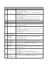
11 Y/CVBS INPUT The Y S-VHS signal of 1Vpp ( inclusive sync amplitude) is AC coupled to pin11.
12 MAIN The TDA8374 has a main supply pin 12 and a horizontal supply pin 37. Both
37 POSITIVE SUPPLY pins have to be supplied simultaneously.
Notice that the IC has not been designed to use this pin 37 as start pin.
(pin 37 supplies the horizontal oscillator, PHI-1 and PHl-2)
(pin 12 supplies the rest of the circuits in the IC)
The nominal supply voltage is 8V. With min/max values of 7.2-8.8V.
Also in stand-by condition the IC must be supplied with 8V.