


32
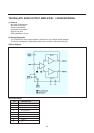
This compensates for the storage time of the horizontal deflection transistor.
The - 2 loop filter (C) is externally connected to pin 42.
The horizontal phase can be given a static off set via I2C-but (HSH “horizontal shift”)
A dynamic correction is possible by current feedback into the - 2 loop filter capacitor.
To protect the horizontal deflection transistor, the ho rizontal drive is switched off immediately when a power
failure ( “ Power-On Reset “ bit POR ) is detected.
The power failure may have corrupted the contents of the internal data registers, so the TDA8374 should be
started up again.
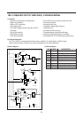
The TDA8374 has a separate supply input (pin 37) that only used as a clean supply voltage for thehorizontal
oscillator circuits.
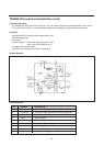
Vertical synchronization
The vertical sawtooth generator drives the vertical output.
It uses an external capacitor at pin 51 and a current reference resistor at pin 52.
The TDA8374 vertical drive has differential current outputs for DC-coupled vertical output stage, like the TDA8356 .
At TDA8356 input pins l and 2 this current is converted into a drive voltage via a resistor.
Geometry processing
With the TDA8374 is possible to implement automatic geometry alignment, because all parameters are adjusted
via the I2C bus.
The deflection processor of the TDA8374 offers the fo11owing five controls;
- Horizontal shift
- Vertical slope.
- Vertical amplitude
- Vertical S-correction
- vertical shift
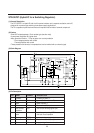
Colour decoder
The colour decoder contains an alignment-free X-tal oscillator, a dual killer circuit and colour difference demodulators.
Together with the TDA8395 SECAM add-on a multi standard PAL/SECAM/NTSC decoder can be built with
automatic recognition.
Which standard can be decoded depends on the external Xtals used.
Two Xtal pins (34and 36) are present so normally no external switching is required.
The I.C. must be told which X-tals are connected (bits XA and XB).
This is important, because the X-tal frequency of the colour decoder is also used to calibrate many internal circuit.
The burst phase detector locks the Xtal oscillator with the chroma burst signal.
The phase detector operates during the burst key period only, to prevent disturbance of the PLL by the chroma signal.
Two gain modes provide:
- Good catching range when the PLL is not Locked.
- Low ripple voltage and good noise immunity once the PLL has locked
The killer circuit switches-off the R-Y and B-Y demodulators at very low input signal conditions (chroma burst amplitude).
A hysteresis prevents on/off switching at low, noisy signals.
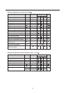
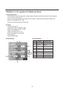
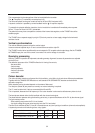
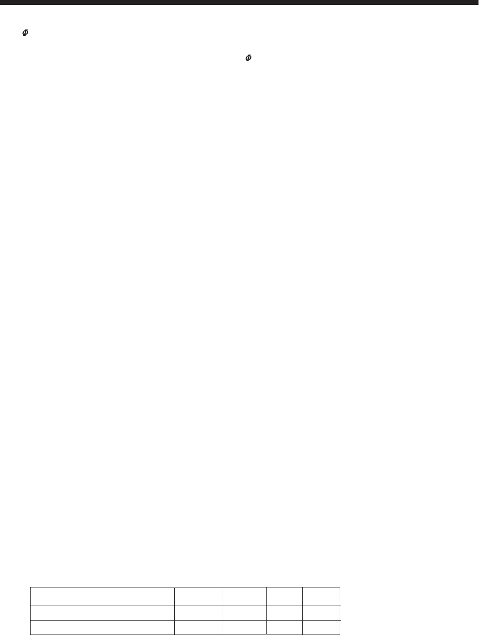
Color standard pin34 pin35 XA XB
PAL4.43/SECAM + NTSC-4.43 none 4.43 1 0
PAL4.43/SECAM + NTSC-M 3.58 4.43 1 1