


31
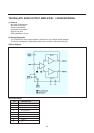
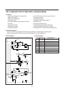
Vision IF amplifier, AFC, video demodulator
The IF signal from the tuner is fed through a SAW filter to the differential IF input (pin 48 and 49).
The first IF stage consists of 3 AC-coupled amplifiers with a total gain control range of over 66 dB.
The reference carrier for the video demodulator is obtained by a PLL carrier regenerator
(eliminating notch filter compromises, as in reference tuned circuits for passive carrier regeneration).
Only an oscillator coil is needed( pin 3 and 4) that can be aligned via l2C-bus to the double IF frequency.
The AFC information is derived from the VCO control voltage of the IF-PLL
and can be read via I2C-bus.
Bit AFB toggles when the picture carrier is exactly at the desired IF frequency (= half the aligned IF-PLL frequency).
AFA is active in a window around this point.
For fast search-tuning applications this window can be increased by a factor 3 (AFW bit).
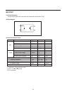
Tuner A.G.C.
The automatic gain control (A.G.C.) circuit operates on top sync level at negative modulated signals
or on peak white level at positive modulation, selected by MOD bit.
The tuner A.G.C. is controlled via pin 54.
The tuner A.G.C. take over point (T.O.P.) can be set over a wide range: 0.8 mVrms .. 80 mVrms
IF input signal amplitude.
The tuner AGC output may have to operate above Vcc of TDA8374.
Therefore pin 54 is an open collector output, that can operate from 0.3 up to Vcc+ 1 Volt
(at > 2 mA sink current)
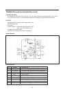
PLL sound demodulator
The IF-video output at pin 6 (2Vpp) is fed through a sound bandpass filter and connected to the intercarrier sound IF
input pin 1.
An alignment free PLL tunes itself to the sound carrier and demodulates it.
The non volume-controlled front-end audio signal can be obtained from the deemphasis pin 55 (amplitude 300 mVeff).
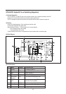
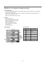
Source select switch
TDA8374 input switch can select one of the following sources ;
pin 13 front-end : CVBS l int
pin17 : CVBS 2 ext
pin 11.pinlO : Y s-vhs, C s-vhs
Selected signal is available at the CVBS output pin 38, in case of Y/C input Y+C are added.
It drive teletext and the TDA8395 SECAM add-on.
For S-VHS applications, the Y,C input can be selected, independent of the CVBS source switch.
TDA8374 Y,C inputs are selected, while the source switch outputs CVBS l int or CVBS 2 ext on CVBS out.
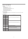
Horizontal synchronization and protection
The synchronization separator adapts its slicing level in the middle between top-sync and black level of the CVBS signal.
The separated synchronization pulses are fed to the first phase detector and to the coincidence detector.
The -1 loop gain is determined by the components at pin 43 (C+RC).
The coincidence detector detects whether the horizontal line oscillator is synchronized to the incoming video.
The line oscillator is a VCO-type, running at twice the line frequency.
It is calibrated with the X-tal oscillator frequency of the colour decoder and has a maximum deviation of 2% of the
nominal frequency, so no alignment is-needed.
Calibration is done at start up( the TDA8374 must first know what colour X-tals are connected, bits XA and XB) and
after synchronization loss ( -1 coincidence detector “Sync Locked” bit SL).
The second phase detector -2 locks the phase of the horizontal driver pulses at output pin 40 to the horizontal
flyback pulse at input pin 41 .
Circuit Description