


17
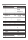
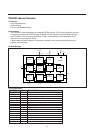
No Name Description
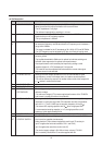
A voltage detection circuit is connected to both pins.
- pin12 if V12 <6.8V than a power on reset, POR, is generated. The Hout
output is disabled immediate.
- pin37 if V37 <5.8V than the horizontal output is disabled immediate.
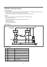
13 INT CVBS INPUT It is recommended that the CVBS1 int and CVBS2 ext input amplitudes are
17 EXT CVBS INPUT 1 Vpp (inclusive sync amplitude).
This, because the noise detector switches the 1 loop to slow mode
(i.e. auto 1mode when FOA, FOB = 0,0) when noise level exceeds
100mVrms (i.e. at S/N of 20dB).
14 GROUND All internal circuits are connected to this ground pin 14.
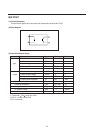
15 AUDIO OUTPUT The output signal is volume controlled and is active for both internal and
external audio signals. The nominal gain is +9dB and -71dB, which gives
a total control range of 80dB.
The output signal range therefor is 0.14- 1400mVrms
The bandwidth is >100kHz, the DC level is 3.3V and the output impedance
is 250 .
16 DECOUPLING Voltage variations at pin 16, which can be due to external leakage current or
FILTER TUNING crosstalk from interference sources, should be less than 50mV to ensure that
tuning of filters/delay cells remains correct.
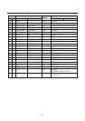
18 BLACK CURRENT For correct operation of the loop CURRENT information is supplied to the
INPUT black current input pin.
19 BLUE OUTPUT The RGB outputs are supplied to the video output stages from pins 21, 20
20 GREEN OUTPUT and 19 respectively.
21 RED OUTPUT For nominal signals (i.e. CVBS/S-VHS, -(R-Y)/- (R-Y), TXT inputs) and for
nominal control settings, then the RGB output Signal amplitudes is
typically 2VBLACK_WHITE.
22 V-GUARD INPUT/ Vertical Guard
BEAM CURRENT With this function, the correct working of the vertical deflection can be
LIMITER monitored. If the vertical deflection fails, the RGB outputs are blanked to
prevent damage to the picture tube.
Beam current limitinq
The beam current limiting function is realised by reducing the contrast (and
finally the brightness) when the beam current reaches s too high level. The
circuit falls apart in two functions:
- Average beam current limiting (ABL): reacting on the average content of
the picture
- Peak white limiting (PWL): reacting on high local peaks in the RGB signal.
23 RED INPUT The Rin, Gin, Bin input signals (nominal signal amplitude of 700mV) are
24 GREEN INPUT AC coupled to pin 23, 24 and 25 respectively.
25 BLUE INPUT Clamping action occurs during burstkey period.
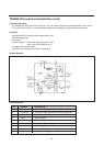
26 RGB INSERTION The table below a survey is given of the three modes which can be selected
SWITCH INPUT with a voltage on RGB insertion switch input pin ;
Vpin26 I2C function Selected RGB signal
0.9V-3V IE1=0 RGB(internal)
IE1=1 Rin,Gin,Bin
(fast insertion on pin23,24,25)
> 4V IE1=X OSD can be inserted at the RGBout pins
27 LUMINANCE INPUT An nominal input signal amplitude of 1 Vblack-white MUST be DC coupled