


5
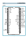
IC DESCRIPTION
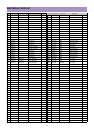
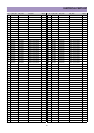
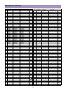
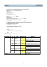
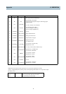
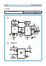
6. Pin Description
PIN Terminal Name Explanation Remarks
1
2
3
4
5
6
7
8
9
10
11
12
13
14
15
16
17
18
19
20
ROM Data Main
IC Data
ROM CLK
Main IC CLK
Tuner Data
Tuner CLK
GND
XT1
XT2
VDD
KEY-IN
AFT-IN
AGC-IN
ST-BY(H)
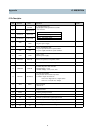
/RES
Filter
CVSB IN
TV/VID
/VS
/HS
R
G
6 bit input/output port
Input/output can be Specified for each bit
Other function.
GND
Negative power supply.
It uses 32.768KHz X-TAL.
10 pin is input terminal for crystal oscillator.
11 pin is output terminal for crystal oscillator.
+5V ( 0.5V)
Positive power supply.
Power, Ch up/down, Vol up/down, Menu
Dc value that comes from the 10 pin of LA76810/14
Connect this port to AGC of Tuner
Default Voltage : 3.75V
Variable Voltage : 3.25V, 3.5V, 4.0V
Use only japan Model.
This port uses when is Stand - By status
Condition : Input AC Power On
Power off : High (DC 5V) Output. (Red)
Power on : Low (DC 0V) Output.
Reset terminal.
Active Low
Filter terminal for PLL
Output terminal
Video signal input terminal
TV Mode : High Line(Video) Mode : Low
Vertical synchronization signal input terminal
Horizental synchronization signal input terminal
Red output terminal of RGB image
Green output terminal of RGB image
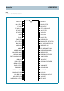
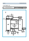
P10/SDA0
P11/SCLK0
P12/SDA1
P13/SCLK1
VSS
XT1
XT2
VDD
P04/AN4
P05/AN5
P06/AN6
P07/AN7
/FES
FILT
CVIN
P01
/VS
/HS
R
G
P10 IIC0 data I/O
P11 IIC0 clock output.
P12 IIC1 data I/O
P13 IIC1 clock output.
Appendix