


6
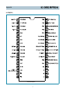
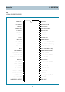
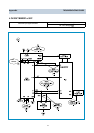
IC DESCRIPTION
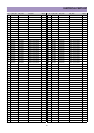
21
22
23
24
25
26
27
28
29
30
31
32
33
34
35
36
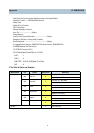
B
BL
Audio Mute
Power On
Bus Stop
Relay On/Off
A/V Detection
Remocon In
RF(H)/AV(L)
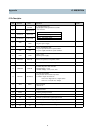
AUTO TINT
PWM VOLUME
BLUE BACK
PRISON
MONO/STEREO
CAPTION
TV ONLY(H)
Blue output terminal of RGB image
Fast blanking control signal
Switch TV image Signal and caption / OSD image signal
Output terminal
Use only read data of LA76814/10
Use when does power off/on
Power off: Output Low(DC 0V)
Power on: Output High(DC 5V)
No Use
Relay On/Off Terminal
Detect port of Front A/V
Input of Remocon Signal
High: RF only mode
Low: RF/AV mode
Low (DC-0V) : On(Auto Tint)
High (DC-5V) : Off
Use only to control Sound of Stereo mode
High (DC-5V) : No Blue Back
Low (DC-0V) : Blue Back
Low (DC-0V) : Normal
High (DC-5V) : Prison
Low (DC-0V) : Mono
High (DC-5V) : Stereo
No Use
Low (DC-0V) : TV/Video
High (DC-5V) : TV Only
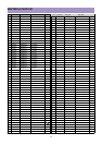
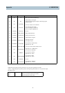
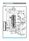
B
BL
P31
P32
P70/INT0
P71/INT1
P72/INT2
P73/INT3
P14/PWM1
P15/PWM2
P16/PWM3
P17
P00
P01
P02
P03
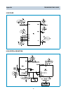
Output form and existence of pull- up resistor for every port can be specified for each bit.
At port 1, Programable pull- up resistor provided when specifing either COOS or N- ch open drain output.
Port status in reset.
Teriminal I/O Pull- up resistor status at selection pull- up option.
Port 0 I Pull- up resistor OFF, ON after reset release.
Port 1 I Programmable pull- resistor OFF.
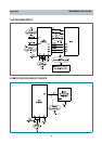
PIN Terminal Name Explanation
Appendix