


30
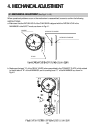
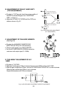
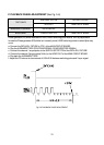
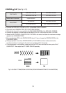
E. X-POSITION ADJUSTMENT
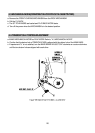
a. Connect the path adjustment fixture to PT01 of the MAIN CIRCUIT BOARD.
b. Play back the ALIGNMENT TAPE (COLOR BAR ALIGNMENT).
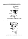
c. Connect channel-1 scope probe to S/W PULSE TEST PIN of PATH ADJ, FIXTURE.
d. Connect channel-2 scope probe to ENVELOPE TEST PIN of PATH ADJ, FIXTURE.
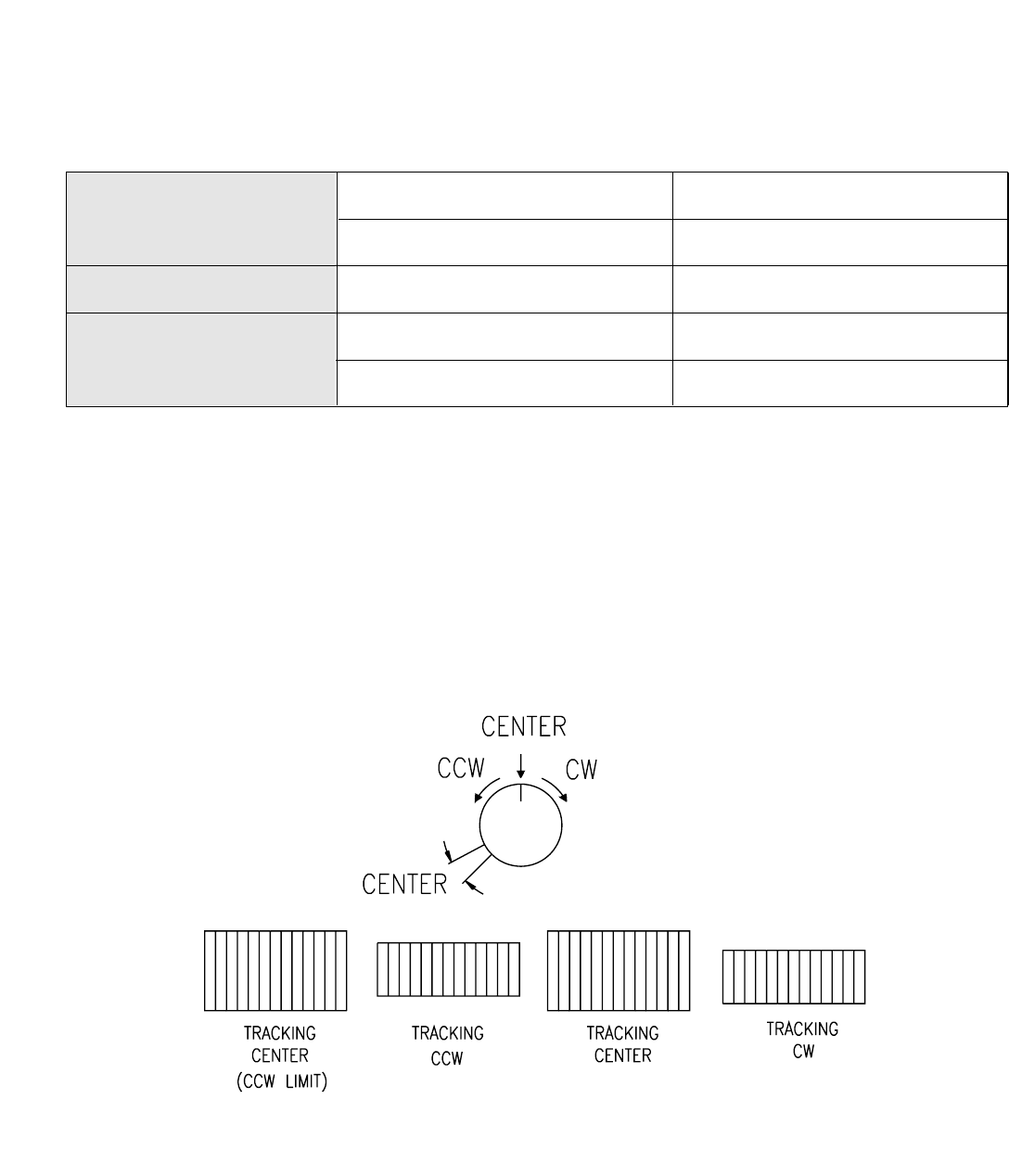
e. Turn the VR CONTROL to the center point. (If the VR CONTROL is completly turned counter-clockwise,
it is positioned on another tracking center.)
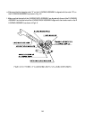
f. With the VR CONTROL in the center state, turn the ADJUST BOSS by using FLAT TYPE SCREW
DRIVER and adjust the X-POSITION to obtain the maximum envelope waveform.
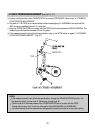
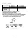
TEST POINTS
S/W PULSE TEST PIN PATH ADJ. FIXTURE
ENVELOPE TEST PIN PATH ADJ. FIXTURE
MEASURING EQUIPMENT OSCILLOSCOPE
ADJUSTMENT
VR CONTROL PATH ADJ. FIXTURE
ADJUST BOSS MAIN BASE.
Fig. 5-5 X-POSITION ADJUSTMENT