


32
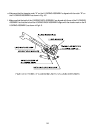
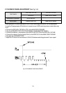
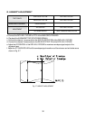
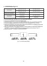
G. LINEARITY ADJUSTMENT
a. Connect the PATH ADJ. FIXTURE to PT01 of the MAIN CIRCUIT BOARD.
b. Play back the ALIGNMENT TAPE (COLOR BAR SIGNAL).
c. Connect the channel-1 scope probe to the S/W PULSE TEST PIN of the PATH ADJ. FIXTURE.
d. Connect the channel-2 scope probe to the ENVELOPE TEST PIN of the PATH ADJ. FIXTURE.
e. Adjust the VR CONTROL of the PATH ADJ. FIXTURE for maximum envelope signal output of the
alignment tape.
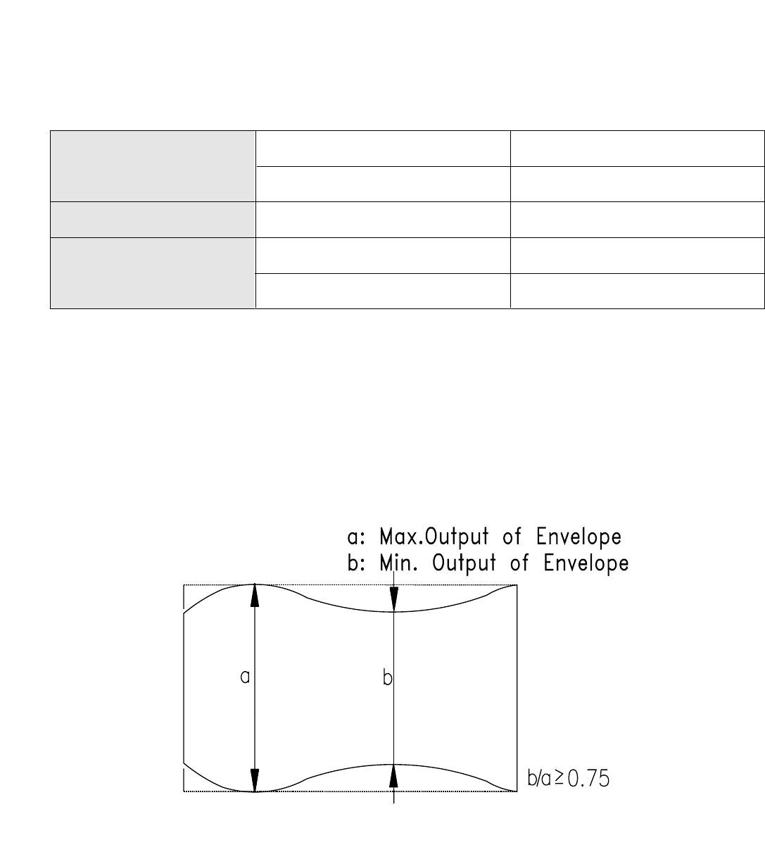
f. Adjust the S/T GUIDE ROLLER until the envelope signal waveforms of the entrance and exit sides are as
shown in Fig. 5-7.
TEST POINTS
S/W PULSE TEST PIN PATH ADJ. FIXTURE
ENVELOPE TEST PIN PATH ADJ. FIXTURE
MEASURING EQUIPMENT OSCILLOSCOPE
ADJUSTMENT
VR CONTROL PATH ADJ. FIXTURE
S/T GUIDE ROLLER TAPE TRANSPORTING SYSTEM
Fig. 5-7 LINEARITY ADJUSTMENT