


36
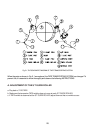
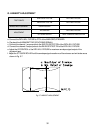
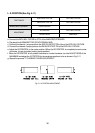
L. X-POSITION (See Fig. 5-11)
a. Connect the PATH ADJ. FIXTURE to PT01 of the MAIN CIRCUIT BOARD.
b. Play back the ALIGNMENT TAPE (COLOR SIGNAL BAR).
c. Connect the channel-1 scope probe to the S/W PULSE TEST PIN of the of the PATH ADJ. FIXTURE.
d. Connect the channel-2 scope probe to the ENVELOPE TEST PIN of the PATH ADJ. FIXTURE.
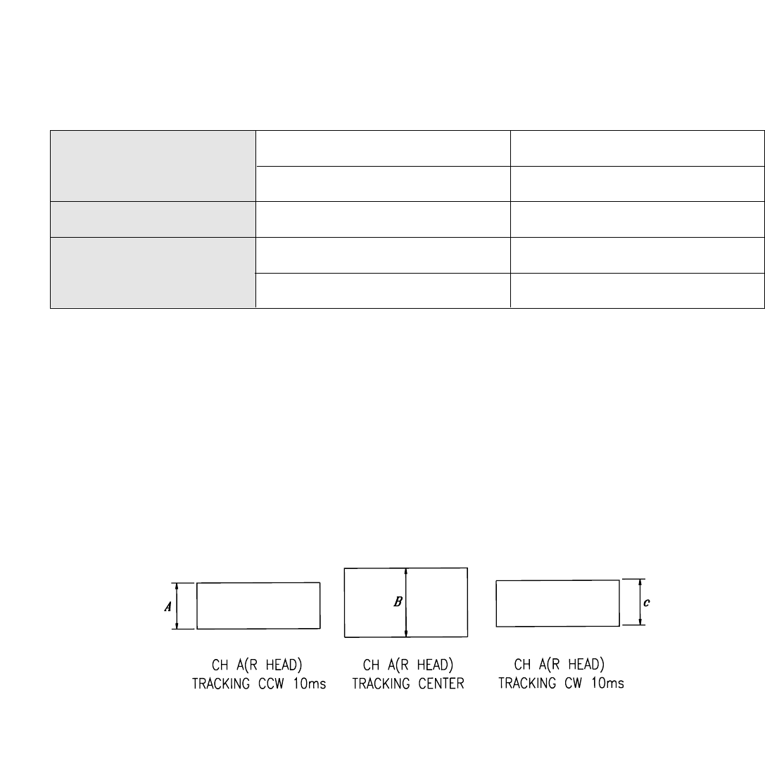
e. Adjust the VR CONTROL to the center position. (When the VR CONTROL is completely turned counter-
clockwise, it is set at another tracking center position).
f. When the VR CONTROL is fully rotated clockwise or counter-clockwise, turn the ADJUST BOSS of the
MAINBASE and adjust the X-POSITION for the envelope waveform to be as shown in Fig. 5-11
g. Repeat the process "F. PLAYBACK PHASE ADJUSTMENT".
TEST POINTS
S/W PULSE TEST PIN PATH ADJ. FIXTURE
ENVELOPE TEST PIN PATH ADJ. FIXTURE
MEASURING EQUIPMENT OSCILLOSCOPE
ADJUSTMENT
VR CONTROL PATH ADJ. FIXTURE
ADJUST BOSS MAIN BASE.
Fig. 5-11 X-POSITION ADJUSTMENT