


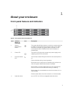
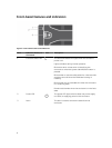

Hard disk drive- status indicator pattern (RAID
Only)
Condition
Blinks green for three seconds, amber for three
seconds, and turns off in six seconds.
Rebuild aborted
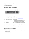
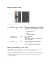
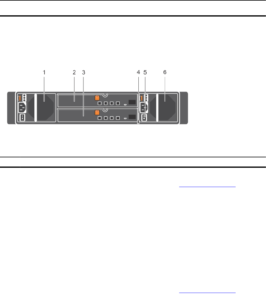
Back-panel features and indicators
Figure 4. Back-panel features and indicators
Item Indicator, Button, or Connector Description
1 Power supply unit or cooling fan
module (PS1)
600 W power supply.
For more information, see Power indicator codes.
2 Primary enclosure management
module (EMM 0)
The EMM provides:
• a data path between the enclosure and the host server.
3 Secondary EMM (EMM 1)
• enclosure management functions for your enclosure.
4 Information tag A slide-out label panel, which allows you to record Service
Tag.
5 Power switches (2) The power switch controls the power supply output to the
enclosure.
6 Power supply unit or cooling fan
module (PS 2)
600 W power supply.
For more information, see Power indicator codes.
Enclosure Management Module
Each EMM provides the following data path and enclosure management functions for your enclosure:
• Monitoring and controlling enclosure environment elements such as temperature, fan, power supply
units, and enclosure LEDs.
• Controlling access to hard disk drives.
• Communicating enclosure attributes and states to the host server.
8